
Description
Hard-Numbers: Technical Specifications
- Input Voltage Range: 24V DC ±10% (some variants: 12-24V DC)
- Channel Capacity: 16 configurable I/O (8 digital inputs/8 digital outputs on some variants, 16 inputs/16 outputs on others)
- Communication Protocol: RS-485 Modbus RTU
- Sampling Rate: 1000 samples/sec
- Measurement Accuracy: ±0.1% across all channels
- Galvanic Isolation: 2500V AC
- Surge Protection: 4kV
- Signal Types Supported: 4-20mA, 0-10V (analog), digital inputs up to 230V AC
- Current Capacity per Channel: 10mA (typical)
- Power Consumption: Max 3W (typical), up to 187 VA on some variants
- Operating Temperature: -20°C to +60°C (some variants: -25°C to +70°C)
- Storage Temperature: -40°C to +85°C
- Protection Rating: IP20 (IP65 on some variants)
- Humidity Range: 5% to 95% non-condensing
- Dimensions: 150 x 90 x 35 mm (typical); 80 x 80 x 25 mm on compact variants
- Weight: 0.06 kg to 0.78 kg (varies by variant and packaging)
- Certifications: CE, UL, RoHS, CSA
- Mounting: DIN rail or pluggable connection (varies by variant)
- Bus Interface: RS-485, CANopen (some variants support both)
The Real-World Problem It Solves
You’re integrating field devices into an ABB AC800M DCS, and ground loops from long cable runs are causing erratic signal readings. Conventional I/O modules without proper isolation let noise from VFDs and high-current equipment corrupt your 4-20mA loops. The YPQ202A’s 2500V AC galvanic isolation breaks ground loops, and the 4kV surge protection survives the inductive kicks from motor starts and contactor switching.
Where you’ll typically find it:
- Power generation turbine control systems interfacing with temperature and pressure transmitters
- Oil & gas SCADA networks connecting remote terminal units to central control rooms
- Chemical plant batch process control with valve positioners and flow meters
- Automotive manufacturing robotic cell control for discrete sensor inputs and actuator outputs
- Wastewater treatment environmental monitoring systems
Bottom line: This board survives the electrical abuse that takes out cheaper I/O modules, keeping your DCS running through power surges and ground noise.

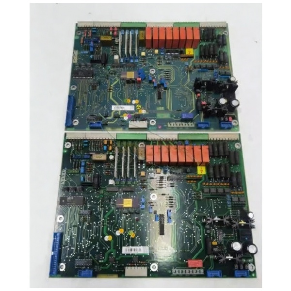
ABB YPQ202A
Hardware Architecture & Under-the-Hood Logic
The YPQ202A is a modular I/O board designed for the ABB Advant Controller 800 series (AC800M platform). It connects to the AC800M controller via the ModuleBus or communication interfaces like CI858. Each channel has individual signal conditioning, and optical coupling provides electrical isolation between field inputs and the internal logic. Input signals are filtered, converted to 5V TTL signals, and transmitted to the CPU unit via the data bus. Digital outputs use transistor switching with current limiting.
Internal signal flow:
- Field device signal enters through terminal block (4-20mA, 0-10V, or digital up to 230V AC)
- Input filter circuit eliminates contact jitter and electrical noise
- Overcurrent/overvoltage/undervoltage protection circuits clamp transients to safe levels
- Optocoupler provides galvanic isolation (2500V AC) between input and internal PLC logic
- Signal converted to 5V TTL level by photovoltaic coupling
- Converted signal sent to input data register on local processor
- Data transmitted via system bus (RS-485 Modbus RTU) to AC800M CPU unit
- For outputs: CPU sends command through data bus to output register
- Output circuit drives field device with current-limited signal
- Channel status LEDs update in real-time for diagnostic feedback
Field Service Pitfalls: What Rookies Get Wrong
Ignoring Ground Loop ProtectionJuniors connect shielded cable shields to ground at both the field device and the cabinet. This creates ground loops, and even with galvanic isolation, you get erratic readings when potential difference exists between earth points.
- Field Rule: Ground shields at the cabinet end only. Let field device floats. If you must ground at both ends, use isolated signal conditioners or verify YPQ202A isolation rating (2500V AC) is adequate for your installation.
Mixing 230V AC and 24V DC on Same Terminal BlockTechs wire high-voltage AC digital inputs adjacent to low-level 4-20mA analog inputs. Cross-talk and capacitive coupling inject noise into analog channels, causing measurement drift.
- Quick Fix: Separate high-voltage and low-voltage wiring. Use different terminal blocks or ensure adequate physical separation (at least 50 mm) between AC and DC signal pairs.
Forgetting to Disable Modbus RTU During Hot-SwapRookies pull the module while the Modbus RTU communication is still active on the network. The master controller times out waiting for the removed node, and the entire bus can hang if termination is incorrect.
- Field Rule: Place the controller in maintenance mode or disable the specific I/O node in Control Builder before hot-swapping. Verify Modbus termination resistors are installed at both ends of the bus.
Overloading Channel Current CapacityTechs wire multiple 4-20mA loops in series through a single channel or attempt to drive 250-ohm test loads with the 10mA output capacity. The channel overheats and fails, or output voltage sags causing incorrect field readings.
- Quick Fix: Verify load impedance matches 4-20mA loop requirements (typically 250-600 ohms total). Use external loop power for high-current loads; use YPQ202A only as signal interface, not power supply.
Neglecting Cold Junction Compensation for ThermocouplesUsing the board for thermocouple inputs but leaving ambient temperature compensation disabled in software. Room temperature changes cause measurement errors that look like sensor drift.
- Field Rule: Enable automatic cold junction compensation in Control Builder parameters. Verify the temperature sensor reference is within operating range (-20°C to +60°C ambient).
Using Unshielded Cable in Electrically Noisy EnvironmentsRunning unshielded cable from VFD proximity switches through cable trays next to power conductors. The board’s built-in filtering gets overwhelmed by EMI, causing false digital inputs and missed state changes.
- Field Rule: Use twisted-pair shielded cable with shield grounded at cabinet only. Keep signal cables at least 300 mm (12 inches) from power cables when possible. Use ferrite cores on long cable runs near termination.
Missing Surge Protection on Field SideRelying solely on the board’s 4kV internal protection without external surge suppressors. Lightning hits or utility switching events induce surges that exceed board protection, damaging input circuits before reaching the surge clamps.
- Field Rule: Install external surge protection devices (SPDs) at the field device end for long cable runs (>100 meters) or outdoor installations. The board’s 4kV protection is your last line of defense, not the first.
Incorrect Modbus RTU Address AssignmentSetting duplicate addresses on multiple YPQ202A modules on the same RS-485 bus. The Modbus master receives garbled responses from overlapping nodes, causing communication failures for all connected boards.
- Quick Fix: Assign unique Modbus addresses (1-247) to each YPQ202A on the bus. Document addresses in the I/O allocation matrix and verify via Modbus scanner tool during commissioning.
Commercial Availability & Pricing Note
Please note: The listed price is for reference only and is not binding. Final pricing and terms are subject to negotiation based on current market conditions and availability.


