
Description
Hard-Numbers: Technical Specifications
- Protocol Support: Profibus DP, CANopen, RS-485, RS-232, Ethernet/IP
- Port Count: 16 Digital Inputs, 8-10 Digital Outputs, Multiple I/O ports
- Baud/Data Rate: Up to 3.5 MIPS processing speed
- Operating Temperature: -20°C to +70°C (some variants +60°C)
- Isolation Rating: 2500V AC
- Power Supply: 24V DC (18-32V range)
- Power Draw: Less than 10W
- Processor: 32-bit ARM Cortex-M7 (alt: Motorola MC68332 at 16MHz for some revisions)
- Memory: 1MB Flash, 256KB RAM (alt: 16KB user memory)
- Dimensions: 150mm x 90mm x 35mm (alt: 11.2cm x 7.7cm x 2cm)
- Certifications: UL 508, IEC 61131-2, CE, RoHS
- Protection Rating: IP20
The Real-World Problem It Solves
Multi-protocol integration headaches on the factory floor. When your control system needs to talk across Profibus DP and CANopen networks without buying separate adapters, this board handles the translation and control logic in one compact package. It eliminates the need for multiple gateways and reduces wiring complexity in control cabinets.
Where you’ll typically find it:
- AMVAC indoor breakers and R-MAG outdoor breakers as the central control board
- Robotics systems requiring safety-critical applications with dual-protocol communication
- Process automation environments where legacy Profibus networks coexist with modern CANopen devices
Bottom line: One board replaces multiple communication modules and cuts down on cabinet heat and failure points.

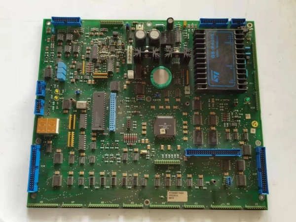
ABB YPQ201A
Hardware Architecture & Under-the-Hood Logic
The YPQ201A sits on the backplane as the intelligence center with its own microprocessor running diagnostics and control logic. It’s isolated from the rest of the system with 2500V AC rating, protecting both the board and downstream equipment from voltage spikes and ground loops.
- Input signal acquisition from 16 digital channels and optional analog inputs
- Protocol translation between Profibus DP, CANopen, and RS-485 networks via the ARM Cortex-M7 processor
- Real-time processing with watchdog, bus supervision, and memory checking continuously running
- CPU load monitoring displayed on-board during normal operation
- Error signals and log values stored in RWM (Read Write Memory) with voltage backup for 12 hours after power loss
- Two-digit LED display shows flashing fault codes for troubleshooting when issues occur
- Output execution through 8-10 digital channels to actuators and downstream devices
Field Service Pitfalls: What Rookies Get Wrong
Improper Grounding During InstallationConnecting the board without establishing a clean earth reference first creates ground loops that trigger intermittent faults or cause erratic communication drops. The watchdog timer catches these as CPU faults, but the root cause is in the cabinet, not the board.Field Rule: Verify chassis ground integrity with a meter before mounting. Use star-topology grounding—tie all grounds to one point on the backplane, not daisy-chained through terminals.
Ignoring Temperature Compensation in Cabinet DesignThe ARM Cortex-M7 processor generates heat during high-speed protocol translation. Overcrowding the cabinet or blocking airflow around the board causes thermal throttling and premature capacitor failure, especially in ambient temperatures above 50°C.Quick Fix: Maintain 2-inch clearance above and below the board. Install forced ventilation if cabinet temperature exceeds 45°C, and monitor the CPU load display during commissioning to catch thermal stress early.
Mixing Signal and Power Wiring in Same ConduitRunning 24V DC power lines alongside low-voltage RS-485 or CANopen communication cables introduces electromagnetic interference that corrupts data packets. The result is intermittent communication timeouts that are impossible to reproduce without a scope.Field Rule: Separate power and signal wiring by at least 6 inches in the cabinet. Use twisted-pair shielded cable for all communications, and ground the shield at one end only—preferably at the controller cabinet.
Forgetting the RWM Battery Backup After Power CyclesThe Read Write Memory holds error logs and fault codes for 12 hours after power loss, but only if the backup circuit is functional. Rookies replace the board after a power cycle because the logs are gone, missing the diagnostic data that would have identified the real failure mode.Quick Fix: Test the backup circuit by pulling 24V power and checking if the LED display remains active for at least 5 seconds. If it dies instantly, the backup capacitor or circuit needs service before deploying in critical applications.
Using the Wrong Wire Gauge for I/O TerminationThe digital I/O terminals require specific torque and wire gauge to maintain contact under vibration. Using oversized wire spreads the terminal and causes intermittent connections that look like sensor failures during operation.Field Rule: Use 18-22 AWG stranded wire with ferrules on I/O connections. Torque terminal screws to manufacturer specs—typically 4-6 in-lbs—and re-torque after the first 24 hours of operation.
Commercial Availability & Pricing Note
Please note: The listed price is for reference only and is not binding. Final pricing and terms are subject to negotiation based on current market conditions and availability.


