
Description
Hard-Numbers: Technical Specifications
- Processor Type: Advanced microcontroller
- Operating Voltage: 220V AC (primary), 24V DC (optional configurations)
- Processing Speed: 100μs response time (specific applications)
- Communication Interface: RS485 (standard), optional MODBUS and CANopen support
- Memory Capacity: On-board RAM for efficient processing; some variants: 32 KB RAM, 256 KB ROM
- Digital Inputs: 3 digital inputs (24-250 V DC or 110-230 V AC)
- Relay Outputs: 2 relay outputs (1250 VA/250 V AC or 5 A/24 V DC)
- Isolation Voltage: 2.5 kV between digital inputs/outputs and power supply (1.5 kV between DI2 and DI3)
- Operating Temperature: -20°C to +60°C
- Storage Temperature: -40°C to +70°C
- Dimensions: 12.7 cm x 10.2 cm x 38.1 cm (38-pin connector module)
- Weight: 1.3 kg (module with connectors)
- Certifications: CE, UL (where applicable)

ABB YPP-105F
The Real-World Problem It Solves
Legacy ABB drive systems require a control card that can handle multiple digital inputs and relay outputs while providing fast response times for precise motor control. The YPP105F module fills this role by serving as the excitation COB board or computer unit within the drive control system, processing control signals and managing communication between field devices and the drive’s main controller. Its on-board RAM and advanced microcontroller enable real-time data processing, essential for applications requiring tight synchronization between motor control and external automation systems.
Where you’ll typically find it:
- ABB TyRak and TyRak Midi drive systems
- Industrial robotic control systems requiring digital I/O interfacing
- Manufacturing automation lines with drive-based motor control
- Material handling systems using ABB drive technology
Reduces control system complexity by integrating digital I/O and processing functions in a single module, eliminating the need for separate interface cards.
Hardware Architecture & Under-the-Hood Logic
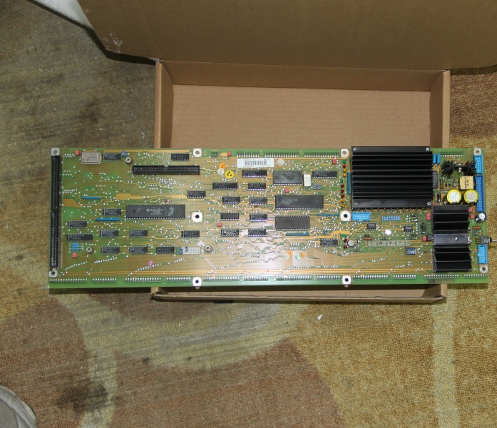
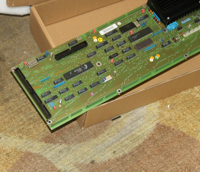
The YPP105F module is designed as a control card that interfaces with ABB drive systems through a 38-pin connector on the RMIO (Remote Input/Output) board. It contains an advanced microcontroller, on-board RAM for data processing, and circuits for digital input conditioning and relay output driving.
- Power is supplied from the drive system through the 38-pin connector (typically 220V AC or 24V DC depending on configuration)
- Digital inputs (DI1, DI2, DI3) accept 24-250 V DC or 110-230 V AC signals from external control devices
- Each digital input passes through isolation circuitry (opto-couplers) before being processed by the microcontroller
- The microcontroller processes input signals based on configured control logic and timing requirements
- On-board RAM provides temporary storage for program execution and data buffering
- Output signals are generated by the microcontroller to drive relay outputs
- Relay outputs (RO1, RO2) are controlled via solid-state or electromechanical relays, providing isolated switching capability
- Communication interfaces (RS485, optional MODBUS/CANopen) enable data exchange with external controllers
- Status and fault conditions are indicated through LED indicators on the module
- The module communicates with the drive’s main controller through the RMIO board backplane connection
ABB YPP-105F
Field Service Pitfalls: What Rookies Get Wrong
Incorrect Slot InstallationTechnicians sometimes insert the YPP105F module into the wrong slot position on the RMIO board. The module must be installed in SLOT 1 or SLOT 2 as marked on the drive.Quick Fix: Always verify the slot marking before installation. The module is designed specifically for SLOT 1 or SLOT 2 positions on the RMIO board. Insert the module carefully until the retaining clips lock it into position, then fasten the two screws that provide earthing and ground interconnection.
Improper DIP Switch ConfigurationThe module features configuration DIP switches that must be set correctly before operation. Rookies often skip this step or set switches incorrectly, leading to communication failures or unexpected behavior.Field Rule: After installing the module, remove the cover to access the DIP switches. Set them according to the application requirements (refer to the drive system documentation for specific switch settings). Refit the cover before powering up the system.
Missing Ground ConnectionThe two screws that secure the module to the stand-offs also provide critical earthing for the I/O cable shield and interconnect the GND signals of the module and RMIO board. New technicians sometimes forget to tighten these screws properly.Field Rule: Always ensure both mounting screws are properly tightened during installation. These screws provide essential grounding that protects against electrical noise and ensures reliable signal transmission between the module and the drive system.
Inadequate Isolation Voltage ConsiderationThe isolation voltage between digital inputs and power supply is 2.5 kV, but the isolation between DI2 and DI3 is only 1.5 kV. Some installers apply incorrect wiring schemes assuming equal isolation between all inputs.Field Rule: Pay attention to the isolation specifications. Never apply voltage levels that exceed the rated isolation between any input pair. Use appropriate external isolation if required by your application. The 1.5 kV isolation between DI2 and DI3 means these inputs should not be used for circuits with high differential voltage requirements.
Neglecting Digital Input Voltage CompatibilityThe module accepts 24-250 V DC or 110-230 V AC on digital inputs. Rookies sometimes connect incompatible voltage levels, risking damage to the input circuitry.Field Rule: Always verify the input voltage range before connecting field devices. The digital inputs are designed for either DC (24-250V) or AC (110-230V) operation, but not for low-voltage TTL/CMOS signals without appropriate signal conditioning.
Commercial Availability & Pricing Note
Please note: The listed price is for reference only and is not binding. Final pricing and terms are subject to negotiation based on current market conditions and availability. This product may be discontinued by the manufacturer, and availability may be limited to third-party suppliers or used equipment providers.


