
Description
Hard-Numbers: Technical Specifications
- Number of Inputs: 8 digital input channels
- Signal Handling Capacity: Up to 100 Hz per channel
- Input Signal Type: Digital speed signals (encoder, tachometer, pulse trains)
- Connection Standard: IEC 61131-2 compliant
- Communication Interface: RS-485, Modbus (where applicable)
- Operating Voltage: DC 24V (standard)
- Power Consumption: Max. 2.5 W
- Operating Temperature Range: -25°C to +60°C
- Storage Temperature Range: -40°C to +70°C
- Dimensions: 5.1 cm x 15.2 cm x 20.3 cm
- Weight: 0.4 kg
- Processor: High-speed digital processing unit
- Memory: Onboard memory for signal processing and data buffering

ABB YPQ110A 3ASD573001A5
The Real-World Problem It Solves
Motor speed control in industrial drive systems requires precise, high-speed digital signal acquisition from encoders and tachometers. The YPM106E module fills this critical role by providing a dedicated interface for digital speed inputs, converting pulse trains from speed sensors into data that the drive controller can process for precise motor control. Its 100 Hz signal handling capability ensures accurate speed feedback even in high-speed applications, while digital isolation protects the control system from electrical noise and ground loops.
Where you’ll typically find it:
- ABB DCS systems requiring digital speed feedback
- Medium and high voltage drive systems with encoder-based speed control
- Turbine and compressor control applications using tachometer inputs
- Paper mills, steel rolling mills, and other precision motor control environments
- Material handling systems requiring accurate speed monitoring
Eliminates speed feedback latency and signal degradation issues by providing dedicated high-speed digital input processing, ensuring precise motor control in demanding industrial applications.
Hardware Architecture & Under-the-Hood Logic
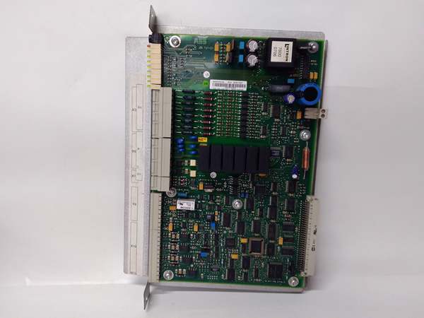
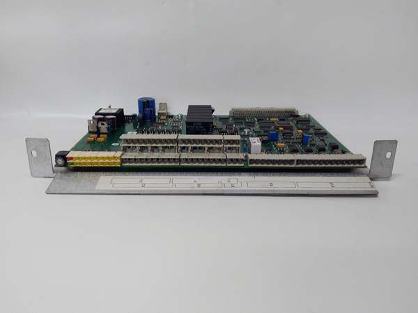
The YPM106E module is designed as a digital speed input interface that connects digital speed sensors (encoders, tachometers, or pulse generators) to the ABB drive or DCS control system. It features high-speed signal conditioning, optical isolation, and digital processing circuitry to ensure accurate and reliable speed feedback.
- Digital speed signals (pulse trains) from encoders or tachometers enter the module’s 8 input channels
- Each input channel passes through signal conditioning circuitry that adjusts signal levels and removes noise
- Opto-isolators provide electrical isolation between field devices and the control system, protecting against ground loops and voltage transients
- A high-speed microcontroller samples and processes the digital pulses, calculating frequency and speed values
- Onboard memory buffers processed data and provides temporary storage for control algorithms
- The processed speed data is transmitted to the drive controller or DCS system via communication interfaces (RS-485/Modbus)
- Status LEDs indicate module operation, signal presence, and fault conditions
- Diagnostic circuitry continuously monitors input signals and reports any abnormalities (signal loss, out-of-range, noise)
ABB YPQ110A 3ASD573001A5
Field Service Pitfalls: What Rookies Get Wrong
Incorrect Signal Voltage MatchingNew technicians often connect speed sensors with output voltages that exceed the module’s input rating, causing damage to the input circuitry. Digital encoders can output 5V, 12V, or 24V signals.Quick Fix: Always verify the speed sensor’s output voltage before connecting to the YPM106E. The module is designed for 24V DC operation. Use appropriate signal conditioning or voltage dividers for sensors with different output voltages.
Mixing Up Encoder Wiring A/B/Z PhasesIncremental encoders typically output A and B quadrature signals plus a Z index pulse. Rookies often wire these incorrectly, resulting in speed calculation errors or direction detection failure.Field Rule: Carefully follow the encoder manufacturer’s wiring diagram and the YPM106E terminal marking. A and B phases must be connected to the correct input terminals with proper phase relationship (90° electrical phase shift) for accurate speed and direction detection.
Ignoring Shield TerminationDigital encoder cables are susceptible to electromagnetic interference (EMI), especially in industrial environments with variable frequency drives. Many technicians neglect proper shield termination, leading to noisy speed signals.Field Rule: Always use shielded twisted-pair cables for encoder connections. Terminate the cable shield at the YPM106E end using the designated shield terminal, following single-point grounding principles. Never leave the shield floating or connect it at both ends (which creates ground loops).
Exceeding Signal Frequency LimitsThe module handles signals up to 100 Hz per channel, but encoders in high-speed applications can output pulse rates exceeding this limit. Rookies often fail to calculate the actual pulse frequency before installation.Field Rule: Calculate the maximum pulse frequency your application will generate: Frequency (Hz) = Motor Speed (RPM) × Encoder PPR (Pulses Per Revolution) ÷ 60. If this exceeds 100 Hz, you need a different module or an encoder with lower PPR.
Hot-Swapping Without Power DownThe module supports communication interfaces, but some technicians attempt to hot-swap cables or modules while the system is powered, risking damage to input circuitry.Field Rule: Always power down the system before connecting or disconnecting encoder cables or removing the module. The 24V input voltage can damage input circuitry if connections are made while powered.
Forgetting to Configure Input FiltersIndustrial environments often have electrical noise that can cause false pulse counting. Many rookies skip input filter configuration, resulting in erratic speed readings.Field Rule: Configure input filter settings according to your application requirements. Longer filter times provide better noise immunity but increase response time. For most applications, start with a filter setting of 5-10 ms and adjust based on observed signal quality.
Commercial Availability & Pricing Note
Please note: The listed price is for reference only and is not binding. Final pricing and terms are subject to negotiation based on current market conditions and availability.


