
Description
Hard-Numbers: Technical Specifications
- Communication Interfaces: RS-232, RS-485, CANopen, Modbus RTU, Ethernet (variant-dependent)
- Communication Protocol: Modbus RTU, CANopen (primary), EtherCAT (variant), Modbus TCP/IP (variant)
- Operating Frequency: 30 kHz (PC board variant), up to 1 MHz (PCB card variant), 300 kHz (advanced variant)
- Input Voltage Range: 12V DC (PCB card variant), 24V DC (primary), 110 V DC AC 12V (alternative variant), 220 V (PC board variant)
- Input Current: Max 200mA
- Processor: 32-bit microcontroller, clock speed 72-120 MHz, up to 2 GHz (advanced variant)
- Memory Capacity: Flash: 512KB-1MB, RAM: 128-256KB, EEPROM: 16-32KB, up to 256 bytes RAM and 4kbytes EEPROM (advanced variant), up to 1 GB RAM and 16 GB ROM (advanced control module)
- Processing Speed: 300 kHz (variant)
- Digital Inputs: 8-16 channels (24V DC, optically isolated)
- Digital Outputs: 4-8 channels (relay or transistor outputs), 16x Digital Outputs (variant)
- Analog Inputs: 4 channels (optional, 0-10V/4-20mA, 12-bit resolution)
- Analog Outputs: 8x Analog Outputs (variant)
- Relay Rating: 5A @ 250V AC/30V DC
- Input Impedance: 3-5 kΩ (digital inputs)
- Operating Temperature Range: -20°C to +60°C (primary), -25°C to +55°C (variant), -40°C to +70°C (industrial grade)
- Storage Temperature Range: -40°C to +85°C
- Humidity Range: 5% to 95% non-condensing
- Cooling Method: Passive Cooling
- Dimensions:
- 16.6 cm x 8.3 cm x 2 cm (circuit board)
- 251917.48 cm (digital output unit)
- 150mm x 100mm x 25mm (industrial control PCB card)
- 145mm x 85mm x 35mm (industrial control module)
- 100 x 100 x 20 mm (PC board variant)
- Weight:
- 0.35 kg (digital output unit)
- 0.36 kg (circuit board)
- 0.415 kg (field input/output module)
- 0.82 kg (field input/output module variant)
- 250 g (industrial control module)
- Shock Resistance: 10 g, 11 ms (variant-dependent)
- Vibration Tolerance: 5 g, 10-500 Hz (variant-dependent)
- Certifications: ISO 9001, CE, UL, CSA (variant-dependent)

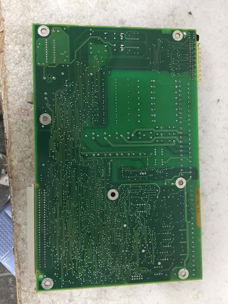
ABB YPQ110A 3ASD573001A5
The Real-World Problem It Solves
Industrial automation systems require reliable signal processing and data acquisition between field devices (sensors, actuators, switches) and control systems (PLCs, DCS, SCADA). The YPK107E module bridges this gap by providing multiple input/output channels with configurable digital and analog interfaces, supporting various industrial communication protocols. Its optical isolation, robust signal processing capabilities, and wide operating temperature range ensure reliable data transmission in harsh industrial environments where electrical noise, temperature extremes, and EMI would otherwise compromise signal integrity and system reliability.
Where you’ll typically find it:
- ABB PLC and DCS control systems as an I/O expansion module
- Industrial automation control panels in manufacturing plants
- Signal conditioning and data acquisition systems in process industries
- Control interface modules in motor control centers
- Digital output units for actuator and device control in automated systems
Eliminates signal noise, voltage spikes, and communication failures through robust isolation and conditioning circuitry, reducing downtime and improving system reliability in critical industrial applications.
Hardware Architecture & Under-the-Hood Logic
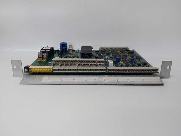
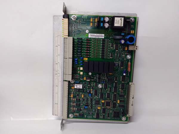
The YPK107E module is designed as a multi-function control board that interfaces with field devices and control systems. It features signal conditioning, protocol conversion, digital and analog I/O processing, and communication interface circuitry to ensure reliable data acquisition and control in industrial automation environments.
- Power is supplied to the module via 12V DC, 24V DC, or 110V DC/AC input (variant-dependent), which is regulated and distributed to internal circuits
- The module features a 32-bit microcontroller (up to 2 GHz in advanced variants) with clock speeds ranging from 72-120 MHz to 2 GHz
- Digital inputs (8-16 channels, optically isolated) receive 24V DC signals from field devices through input impedance of 3-5 kΩ, providing electrical isolation and noise immunity
- Digital outputs (4-8 channels, up to 16x in variants) provide relay (5A @ 250V AC/30V DC) or transistor outputs to control external devices
- Analog inputs (optional, 4 channels) accept 0-10V or 4-20mA signals with 12-bit resolution, processed through ADC (analog-to-digital converter)
- Analog outputs (8x in variants) provide controlled analog output signals for device control
- Communication interfaces support multiple protocols:
- RS-232 serial communication (point-to-point)
- RS-485 multi-drop communication for Modbus RTU
- CANopen for industrial automation networks
- Modbus RTU protocol stack for PLC/SCADA integration
- Ethernet for TCP/IP communication (variants)
- EtherCAT for high-speed real-time control (advanced variant)
- Memory (Flash: 512KB-1MB, RAM: 128-256KB, EEPROM: 16-32KB, up to 1 GB RAM and 16 GB ROM in advanced variants) provides data buffering, program storage, and configuration parameter retention
- Protocol conversion logic enables seamless data exchange between different fieldbus protocols
- Status LEDs indicate communication activity, I/O status, and fault conditions
- Diagnostic circuitry monitors input/output signal quality and reports errors
- Passive cooling ensures reliable operation without active cooling components
ABB YPQ110A 3ASD573001A5
Field Service Pitfalls: What Rookies Get Wrong
Incorrect Input/Output WiringNew technicians often mix up digital input and output wiring, leading to incorrect signal routing or potential damage to I/O circuits.Quick Fix: Always verify the I/O channel type before wiring. Use the module’s pinout diagram and color-code wires according to your plant’s standards. Double-check that 24V DC inputs are connected to designated input terminals and outputs are connected to appropriate output terminals. Use a multimeter to verify signal levels before connecting to the module.
Mismatched Communication ProtocolsThe module supports multiple communication protocols (RS-232, RS-485, CANopen, Modbus RTU, Ethernet), and rookies sometimes configure the wrong protocol for the application, causing communication failures.Field Rule: Verify the required communication protocol before installation. Configure the module’s communication parameters (baud rate, data bits, parity, stop bits) according to your plant network topology. Use ABB’s configuration software or the module’s DIP switches/jumpers to set the correct protocol. Ensure that the connected control system (PLC, DCS, SCADA) is configured to use the same protocol.
Inadequate Signal GroundingImproper grounding of digital and analog inputs can cause signal noise, measurement errors, and intermittent communication failures.Field Rule: Ensure proper grounding of all signal cables. Connect the module’s ground terminal to the control system’s common ground plane. Use shielded cables for analog signals and connect the shield to ground at one end only (typically at the control system end) to avoid ground loops. For digital inputs, maintain consistent reference ground levels.
Overloading Digital OutputsTechnicians sometimes exceed the relay rating (5A @ 250V AC/30V DC) or connect inductive loads without proper protection, causing relay contacts to weld or fail.Field Rule: Never exceed the specified relay rating. For inductive loads (motors, solenoids), install flyback diodes or suppression circuits across the load terminals to protect the relay contacts from voltage spikes. Consider using solid-state outputs for high-frequency switching applications.
Improper Analog Signal ScalingAnalog inputs (0-10V/4-20mA) require proper scaling to match the sensor range. Rookies often configure incorrect scaling parameters, leading to measurement errors.Field Rule: Configure the analog input scaling parameters according to the sensor’s output range and the desired engineering units. Use the module’s configuration software to set the minimum and maximum input values corresponding to the sensor’s output range. Verify the scaling by applying known test signals and confirming the measured values.
Neglecting Optical Isolation LimitsDigital inputs are optically isolated, but isolation voltage and current limits must be respected. Exceeding these limits can damage the isolation circuitry.Field Rule: Ensure that the input signals (24V DC) are within the specified input voltage range. Do not exceed the maximum input current (typically < 20mA per channel). For applications requiring higher voltage inputs, use external signal conditioning circuits to step down the voltage to the module’s input range.
Hot-Swapping I/O ModulesSome technicians attempt to connect or disconnect field wiring while the module is powered, potentially damaging the input/output circuitry.Field Rule: Never hot-swap field wiring. Power down the control system before connecting or disconnecting field devices. The I/O circuits are not designed for hot-swap and can be damaged by inrush currents or ESD events during insertion/removal.
Ignoring LED Diagnostic IndicatorsThe module has status LEDs that provide valuable diagnostic information, but inexperienced technicians ignore them during troubleshooting.Field Rule: Learn to read the LED indicators:
- Power LED: Should be solid green when powered
- Communication LEDs (RX/TX): Blink with data transmission
- Digital Input LEDs: Illuminated when input is active (high state)
- Digital Output LEDs: Illuminated when output is active
- Fault/Error LED: Illuminates red on module faults or communication errors
Incorrect Module AddressingIn multi-module configurations, each module requires a unique address. Rookies sometimes duplicate addresses, causing communication conflicts.Field Rule: Assign a unique address to each module in the network. Use the module’s address DIP switches or configuration software to set the address. Ensure that no two modules on the same communication bus have the same address. Document the assigned addresses for future reference.
Inadequate ESD PrecautionsThe module contains sensitive electronic components that can be damaged by electrostatic discharge during handling and installation.Field Rule: Always use ESD precautions when handling the module. Wear an anti-static wrist strap connected to ground, and handle the module by its edges. Avoid touching the circuitry directly. Store the module in anti-static packaging when not in use.
Commercial Availability & Pricing Note
Please note: The listed price is for reference only and is not binding. Final pricing and terms are subject to negotiation based on current market conditions and availability. This product is part of ABB’s industrial automation product line and may have different availability through various distribution channels depending on the specific variant and regional supply chain.


