
Description
Hard-Numbers: Technical Specifications
- Measurement Type: Power
- Measurement Accuracy: ±0.1% to ±0.5% of reading (variant-dependent)
- Resolution: 0.01% (power meter), 0.01 A (current measurement)
- Input Voltage Range:
- 100V to 240V AC (power meter)
- 10VDC to 30VDC (variant)
- 12V DC (PLC variant)
- 24V DC (PLC variant)
- Output Signal: 4-20mA (analog output)
- Communication Interface: RS-485 (primary), RS-232 (variant)
- Communication Protocol: Modbus RTU (primary), Modbus TCP/IP (variant), Ethernet/IP (variant)
- Number of Channels: 4 measurement channels
- Operating Temperature Range:
- -20°C to +55°C (primary)
- -25°C to +60°C (variant)
- -10°C to +50°C (variant)
- -20°C to +70°C (variant)
- Storage Temperature Range: -40°C to +85°C
- Power Consumption: ≤1W (variant)
- Power Rating: 200W (variant)
- Programming Language: Ladder Logic (PLC variant)
- Memory Capacity: 10 KB (PLC variant)
- I/O Ports: 24 Input, 16 Output (PLC variant)
- Dimensions:
- 114mm x 110mm x 15mm (primary)
- 11.4 cm x 11 cm x 1.5 cm (variant)
- 150mm x 100mm x 30mm (variant)
- 5.8cm x 5.8cm x 1.8cm (fiber optic variant)
- Weight:
- 0.1 kg (primary)
- 0.107 kg (variant)
- 0.5 kg (variant)
- Certifications: CE, UL, CSA (variant-dependent)
- Protection Rating: IP20 (variant)
- Material: High-grade aluminum alloy (variant)

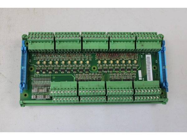
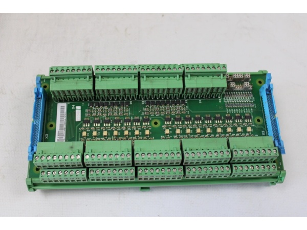
ABB YPG111A
The Real-World Problem It Solves
Industrial automation systems require precise monitoring of electrical power consumption and parameters to optimize energy efficiency, prevent equipment damage, and ensure process reliability. The YPG111A module addresses this need by providing high-accuracy power measurement (±0.1% to ±0.5%) with real-time data acquisition and communication capabilities. Its ability to measure voltage, current, power factor, and power consumption, combined with Modbus RTU communication and 4-20mA analog output, enables seamless integration with PLCs, DCS, SCADA systems, and energy management platforms, allowing operators to monitor power usage trends, detect anomalies, and implement energy-saving strategies in manufacturing facilities, power plants, and process industries.
Where you’ll typically find it:
- Industrial automation control panels for power monitoring
- Energy management systems in manufacturing plants
- Power distribution panels with measurement capabilities
- PLC and DCS systems requiring power measurement integration
- Motor control centers with power consumption monitoring
- Energy efficiency monitoring systems in process industries
Provides accurate real-time power data with ±0.1% accuracy, enabling energy optimization, predictive maintenance, and cost reduction through precise power consumption tracking and anomaly detection.
Hardware Architecture & Under-the-Hood Logic
The YPG111A module is designed as a high-precision power measurement unit that interfaces with electrical power systems and control networks. It features voltage and current sensing circuitry, signal conditioning, analog-to-digital conversion, communication interfaces, and analog output capabilities to ensure accurate power parameter measurement and data transmission in industrial automation environments.
- Power is supplied to the module via 12V DC, 24V DC, or 100-240V AC input (variant-dependent), which is regulated and distributed to internal circuits
- Voltage sensing circuitry measures AC or DC voltage through high-precision voltage dividers and isolation amplifiers, providing electrical isolation and safety
- Current sensing circuitry measures current through Hall effect sensors or current transformers (CTs), converting current signals to voltage for processing
- Signal conditioning circuits amplify, filter, and linearize the raw voltage and current signals to improve measurement accuracy
- Analog-to-digital converters (ADC) with high resolution (0.01% for power measurements, 0.01 A for current) convert conditioned analog signals to digital values
- Digital signal processor calculates derived power parameters including:
- Active power (W)
- Reactive power (VAR)
- Apparent power (VA)
- Power factor (PF)
- Total harmonic distortion (THD)
- Memory (up to 10 KB in PLC variants) provides data buffering, calibration parameters, and configuration storage
- Communication interface (RS-485 primary) enables Modbus RTU communication with PLCs, DCS, and SCADA systems
- Modbus RTU protocol stack processes outgoing measurement data and incoming configuration commands
- Digital-to-analog converter (DAC) provides 4-20mA analog output for proportional representation of selected measurement parameters
- Diagnostic circuitry continuously monitors measurement accuracy, communication integrity, and internal fault conditions
- Status LEDs indicate power status, communication activity, measurement validity, and fault conditions
- In PLC variants, additional I/O ports (24 digital inputs, 16 digital outputs) provide control and monitoring capabilities
- Programming support for Ladder Logic and Structured Text (PLC variants) enables custom control logic implementation
ABB YPG111A
Field Service Pitfalls: What Rookies Get Wrong
Incorrect CT (Current Transformer) OrientationNew technicians often install current transformers in the wrong direction, causing negative current readings or measurement errors.Quick Fix: Verify the correct CT orientation by checking the polarity markings (H1/H2 or primary/secondary labels) on the CT and the module. The primary current should flow from H1 to H2, and the secondary polarity must match the module’s input requirements. If readings are negative, swap the secondary connections.
Improper Voltage Range ConfigurationThe module supports multiple input voltage ranges (100-240V AC, 10-30V DC, etc.), and rookies sometimes configure the wrong range, leading to measurement inaccuracies or potential damage.Field Rule: Before applying power, verify the actual system voltage and configure the module’s input range accordingly. Use the module’s configuration software or DIP switches to select the appropriate voltage range. Never exceed the specified maximum input voltage for the configured range.
Neglecting CT Ratio ConfigurationCurrent transformers have various ratios (e.g., 100:5, 200:5), and the module must be configured to match the installed CT ratio for accurate current measurement.Field Rule: Identify the CT ratio from the CT nameplate or documentation and configure the module’s CT ratio parameter in the Modbus registers. Incorrect CT ratio settings will result in proportional measurement errors (e.g., configuring 100:5 when a 200:5 CT is installed will cause readings to be half the actual value).
Poor Grounding PracticesImproper grounding of the module and current transformer secondary circuits can cause measurement noise, safety hazards, and equipment damage.Field Rule: Ensure the module’s ground terminal is properly connected to the system’s protective earth (PE) using appropriate gauge wire. The current transformer secondary circuit should have one side grounded per IEEE and IEC standards (typically at the module). Never leave the CT secondary floating, as high voltages can develop during fault conditions.
Modbus Communication Address ConflictsIn multi-device networks, each device requires a unique Modbus address. Rookies sometimes duplicate addresses, causing communication failures.Field Rule: Assign a unique Modbus address to each YPG111A module on the RS-485 network. Use the module’s address DIP switches or configuration software to set the address. Ensure no two devices share the same address. Document the assigned addresses for future reference and troubleshooting.
Analog Output Scaling ErrorsThe 4-20mA analog output requires proper scaling to represent the desired measurement range (e.g., 0-100kW). Incorrect scaling leads to misrepresentation of the measured value at the receiving device.Field Rule: Configure the analog output scaling parameters according to the expected measurement range and the receiving device’s input range. Use the module’s configuration software to set the minimum (4mA) and maximum (20mA) output values corresponding to the desired measurement range. Verify the scaling by applying known load conditions and confirming the output current.
Ignoring Power Factor Measurement IssuesPower factor measurements require both voltage and current inputs. Rookies sometimes connect only one input, leading to incorrect or zero power factor readings.Field Rule: Ensure both voltage and current inputs are properly connected for power factor and power measurements. Verify phase relationships (e.g., for three-phase systems, connect voltage and current from the same phase). Use phase angle indicators or reference phasors to confirm correct phase alignment.
Overloading Analog Output CircuitThe 4-20mA output has a maximum load resistance specification. Exceeding this limit causes the output to saturate, providing incorrect readings.Field Rule: Calculate the total loop resistance including the receiving device’s input resistance and wire resistance. Ensure the total resistance is within the module’s specified maximum load (typically 500-600 ohms for 24V supply). Use external signal conditioners if the loop resistance exceeds the limit.
Hot-Swapping Measurement ConnectionsSome technicians attempt to connect or disconnect voltage and current measurement wiring while the system is powered, potentially damaging the module or creating safety hazards.Field Rule: Never hot-swap measurement connections. Power down the measurement circuit before connecting or disconnecting voltage and current inputs. The measurement circuits are not designed for hot-swap and can be damaged by inrush currents or arcing during insertion/removal.
Neglecting LED Diagnostic IndicatorsThe module has status LEDs that provide valuable diagnostic information, but inexperienced technicians ignore them during troubleshooting.Field Rule: Learn to read the LED indicators:
- Power LED: Should be solid green when powered
- Communication LED (RX/TX): Blinks with Modbus communication
- Measurement Valid LED: Illuminated when measurements are within valid range
- Fault/Error LED: Illuminates red on measurement errors or module faults
Calibration Verification NeglectHigh-accuracy power meters (±0.1%) require periodic calibration verification. Rookies assume factory calibration remains accurate indefinitely.Field Rule: Periodically verify the module’s calibration accuracy using reference measurement equipment or a calibrated power standard. Document calibration dates and results. If accuracy degrades beyond specifications, perform calibration adjustment or return the module for factory recalibration.
Commercial Availability & Pricing Note
Please note: The listed price is for reference only and is not binding. Final pricing and terms are subject to negotiation based on current market conditions and availability. This product is part of ABB’s industrial automation and power measurement portfolio and may have different availability through various distribution channels depending on the specific variant and regional supply chain.

