
Description
Hard-Numbers: Technical Specifications
- Product Type:
- Display Unit Board (primary)
- Digital Output Control Board (variant)
- Output Expansion Module (variant)
- Analog Input Card (variant)
- Central Unit (variant)
- Number of Channels:
- 16 channels (digital output control board)
- Multiple output channels (expansion module)
- Variable based on configuration
- Rated Insulation Voltage: 50 V (digital output control board)
- Power Rating:
- 110W (control board variant)
- Typical 4.3W (digital output control board)
- Power Dissipation: Typical 4.3 W (digital output control board)
- Input Voltage Range:
- 90-250V AC (control board variant)
- 24 V DC (digital display module variant)
- Variable based on application
- Current Capacity: 20A (control board variant)
- Output Frequency: 0-50Hz (control board variant)
- Communication Protocol:
- Modbus RTU (primary)
- Ethernet (variant)
- RS-232 (variant)
- RS-485 (variant)
- Communication Interfaces:
- 2 x Ethernet (digital display module variant)
- 1 x RS-232 (digital display module variant)
- RS-485 (variant)
- Variable based on variant
- Memory Capacity:
- 2Kbytes EEPROM (control board variant)
- 256 KB RAM, 1 MB ROM (processor unit variant)
- 128 MB RAM, 512 MB Flash (digital display module variant)
- Processor Speed:
- 400 MHz (digital display module variant)
- Up to 1 MHz (processor unit variant)
- Operating Temperature Range:
- -20°C to +60°C (primary)
- -10°C to +50°C (variant)
- -20°C to +55°C (variant)
- Storage Temperature Range:
- -40°C to +70°C (processor unit variant)
- Not specified (other variants)
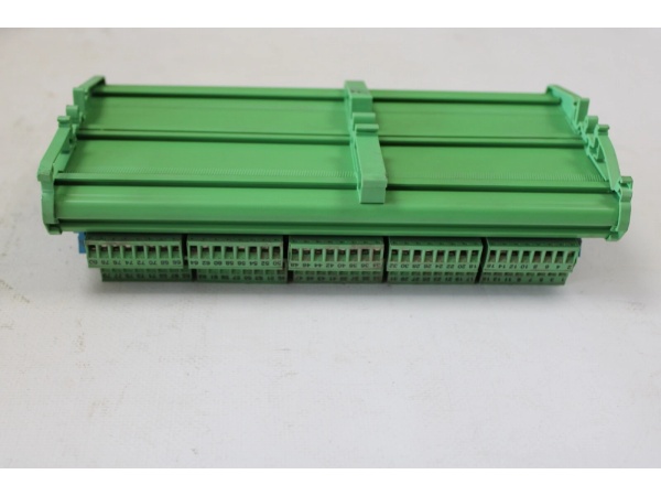
- Dimensions:
- 102mm x 119mm x 45mm (digital output control board)
- 14.8 cm x 7.5 cm x 1.5 cm (display unit board)
- 100mm x 80mm x 40mm (control board variant)
- 230mm x 140mm x 100mm (processor unit variant)
- 94mm x 94mm x 51mm (digital display module variant)
- Weight:
- 0.08 kg (display unit board)
- 0.15 kg (digital output control board)
- 0.5 kg (processor unit variant)
- 0.78 kg (control board variant)
- 150 g (digital display module variant)
- Certifications: CE, UL, CSA (variant-dependent)
- Protection Rating: IP20 (digital display module variant)
- Special Features:
- Input load resistor on soldering posts (display unit board)
- Windows Embedded Standard 7 (digital display module variant)

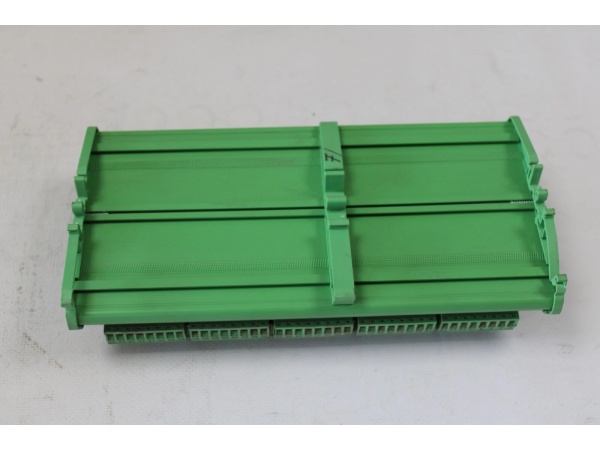
ABB YPG111A
The Real-World Problem It Solves
Industrial automation systems require versatile interface solutions that combine display capabilities, digital output control, and analog input processing for comprehensive system integration. The YPG110E module addresses this need by providing multi-functionality as a display unit board, digital output control board, output expansion module, or analog input card depending on configuration. Its 16-channel digital output capability with 50V insulation voltage, combined with Modbus RTU communication and various interface options (Ethernet, RS-232, RS-485), enables flexible integration with ABB PLC and DCS systems. The module supports diverse automation applications from process control to manufacturing, providing visual feedback, control signal output, and analog data acquisition in harsh industrial environments with wide temperature tolerance (-20°C to +60°C).
Where you’ll typically find it:
- ABB PLC and DCS control panels as interface and output control
- Industrial automation systems requiring display units and digital outputs
- Process control systems with analog input and output requirements
- Bailey network distributed control systems
- Manufacturing facilities with integrated control and display needs
- Industrial applications requiring expansion of output channels
Provides flexible multi-functionality with 16-channel digital output capability, display interface, and analog input processing, enabling comprehensive system integration and control in diverse industrial automation applications from process control to manufacturing.
Hardware Architecture & Under-the-Hood Logic
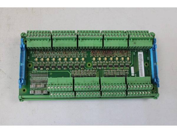
The YPG110E module is designed as a versatile control board that serves multiple functions depending on configuration: display unit, digital output control, output expansion, or analog input connection. It features microprocessor-based control circuitry, communication interfaces, output driving circuitry, and display interface capabilities to ensure flexible integration with ABB PLC and DCS systems.
- Power is supplied to the module via 90-250V AC (control board variant), 24V DC (display module variant), or variable voltage depending on application, which is regulated and distributed to internal circuits
- Microprocessor unit (up to 1 MHz to 400 MHz depending on variant) processes control logic and manages module operations
- Memory (2Kbytes EEPROM to 512 MB Flash depending on variant) provides data buffering, configuration storage, and programming retention
- Digital output control circuitry (16 channels, 50V insulation voltage) drives external devices through:
- Opto-isolated output drivers for electrical isolation and noise immunity
- Relay or transistor output circuits depending on channel configuration
- Overload and short-circuit protection for each output channel
- Display interface circuitry (display unit board variant) drives LED or LCD displays for:
- Real-time process data visualization
- System status indication
- Alarm and fault message display
- Parameter configuration interface
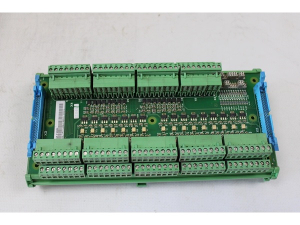
- Analog input processing circuitry (analog input card variant) conditions and processes analog signals through:
- Signal conditioning amplifiers and filters
- Analog-to-digital converters (ADC)
- Input load resistors on soldering posts for signal termination
- Communication interfaces enable data exchange with control systems:
- Modbus RTU protocol stack (primary)
- Ethernet interfaces (10/100 Mbps) for high-speed communication
- RS-232 serial communication for point-to-point connections
- RS-485 multi-drop communication for network integration
- Communication protocol processing handles outgoing data (measurement values, status) and incoming commands (configuration, control signals)
- Diagnostic circuitry continuously monitors output status, communication integrity, and internal fault conditions
- Status LEDs indicate power status, communication activity, output channel status, and fault conditions
- In display module variants with Windows Embedded Standard 7, additional processing capabilities enable advanced HMI functionality
- Output expansion module circuitry provides additional output channels for system scalability
- The module integrates with ABB’s automation ecosystem through standardized interfaces and protocols
- Power dissipation management (typical 4.3W) ensures efficient operation and thermal management
ABB YPG111A
Field Service Pitfalls: What Rookies Get Wrong
Incorrect Module Configuration IdentificationThe YPG110E exists in multiple variants (display unit, digital output control, output expansion, analog input), and rookies sometimes fail to identify the correct variant before installation.Quick Fix: Always verify the module variant by checking the model number, type number (YT204001-FD or YT204001-FD1), and functional description on the module label. Consult the module’s documentation or ABB’s catalog to confirm the variant-specific configuration before installation. Different variants require different wiring and configuration procedures.
Overloading Digital Output ChannelsThe 16 digital output channels have specified current and voltage ratings (50V insulation voltage). Rookies sometimes connect loads exceeding these ratings, causing output failures or module damage.Field Rule: Never exceed the specified output channel ratings. Calculate the total load current and voltage for each channel. Ensure that inductive loads (motors, solenoids) have appropriate suppression circuits (flyback diodes, RC networks) to protect output drivers from inductive kickback. Consider using external relays for high-current or high-voltage loads.
Improper Input Load Resistor InstallationThe display unit board variant features input load resistors on soldering posts. Rookies sometimes install incorrect resistor values or fail to connect them properly, causing measurement errors.Field Rule: Identify the required input load resistor value from the module’s documentation based on the input signal type and sensor specifications. Use precision resistors (1% tolerance or better) and ensure proper soldering technique. Verify resistor installation with a multimeter to confirm the correct resistance value is present between the specified terminals.
Modbus Communication Address ConflictsIn multi-device networks, each module requires a unique Modbus address. Rookies sometimes duplicate addresses, causing communication failures.Field Rule: Assign a unique Modbus address to each YPG110E module on the RS-485 network. Use the module’s address DIP switches or configuration software to set the address. Ensure no two devices share the same address. Document the assigned addresses for future reference and troubleshooting.
Neglecting Output Isolation RequirementsThe digital output channels are opto-isolated for electrical safety and noise immunity. Rookies sometimes connect outputs without considering isolation requirements, leading to ground loops or noise issues.Field Rule: Understand the isolation characteristics of each output channel. For applications requiring electrical isolation between the module and the load, utilize the opto-isolated outputs properly. Avoid connecting isolated outputs to common grounds on the load side unless intentional. Use isolation barriers when interfacing with equipment at different ground potentials.
Incorrect Display Interface WiringThe display unit board variant requires proper connection to display elements. Rookies sometimes wire displays incorrectly, resulting in no display or garbled characters.Field Rule: Follow the display wiring diagram in the module’s documentation carefully. Verify the display type (LED segment, LCD, etc.) and ensure the wiring matches the display’s pinout. Use appropriate gauge wire for display connections and verify continuity with a multimeter before powering the system.
Power Supply Voltage MismatchDifferent YPG110E variants require different input voltages (90-250V AC for control boards, 24V DC for display modules). Rookies sometimes apply the wrong voltage, damaging the module.Field Rule: Always verify the required input voltage for the specific YPG110E variant before connecting power. Check the module’s rating plate and documentation for the specified voltage range. Use a multimeter to verify the actual supply voltage before connection. Never apply AC voltage to DC-input modules or vice versa.
Overlooking Diagnostic LED IndicationsThe module has status LEDs that provide valuable diagnostic information, but inexperienced technicians ignore them during troubleshooting.Field Rule: Learn to read the LED indicators:
- Power LED: Should be solid green when powered
- Communication LED (TX/RX): Blinks with Modbus communication
- Output Channel LEDs: Illuminated when corresponding output is active
- Fault/Error LED: Illuminates red on module faults or communication errors
- Display Status LED (display variants): Indicates display functionality
Analog Input Signal Grounding IssuesThe analog input card variant requires proper signal grounding for accurate measurements. Rookies sometimes introduce ground loops or improper grounding, causing measurement errors.Field Rule: Follow proper grounding practices for analog inputs. Use shielded cables for analog signal connections and connect the shield to ground at one end only (typically at the control system end). Maintain proper isolation between analog input channels when required. Verify signal integrity with an oscilloscope if measurement accuracy is critical.
Hot-Swapping Module ConnectionsSome technicians attempt to connect or disconnect field wiring while the system is powered, potentially damaging the module or creating safety hazards.Field Rule: Never hot-swap module connections. Power down the control system before connecting or disconnecting field devices. The module’s input/output circuits are not designed for hot-swap and can be damaged by inrush currents or arcing during insertion/removal.
Neglecting Windows Embedded Standard 7 MaintenanceThe digital display module variant runs Windows Embedded Standard 7 operating system, which requires periodic maintenance and updates. Rookies sometimes ignore OS-level maintenance.Field Rule: For display module variants with Windows Embedded Standard 7, implement regular maintenance procedures including:
- Disk cleanup and defragmentation
- Security updates and patches from Microsoft (within compatibility requirements)
- Application software updates from ABB
- Regular backup of critical configuration files
- Monitoring system resources (CPU, memory, disk space) for optimal performance
Commercial Availability & Pricing Note
Please note: The listed price is for reference only and is not binding. Final pricing and terms are subject to negotiation based on current market conditions and availability. This product is part of ABB’s industrial automation and Bailey/DCS systems portfolio and may have different availability through various distribution channels depending on the specific variant and regional supply chain.


