
Description
Hard-Numbers: Technical Specifications
- Product Type:
- Analog Input Board (primary)
- Programmable Controller Module (variant)
- Control Board (variant)
- Number of Channels:
- 8 channels (analog input board – primary)
- 4 channels (variant)
- Variable based on configuration
- Input Signal Range:
- ±10 V (primary)
- 4-20 mA (supported)
- -10V to +10V (variant)
- Resolution:
- High resolution (analog input board)
- 12-bit (variant)
- Accuracy/Precision:
- ±0.05% (analog input board – primary)
- Sampling Frequency:
- Fast sampling rates for dynamic applications
- 5 kHz (related model YPG109A reference)
- Communication Protocol:
- DeviceNet (variant)
- Modbus RTU (related model reference)
- Power Supply:
- DC 5V (variant)
- 100V to 240V AC (related model reference)
- Operating Temperature Range:
- -25°C to +60°C (variant)
- -20°C to +60°C (primary)
- Storage Temperature Range: Not specified in sources
- Dimensions:
- 24 x 9.1 x 2.5 cm (9.45 x 3.58 x 0.98 inches) (analog input board – primary)
- 11.5 x 11 x 3.5 cm (variant)
- 11.5 cm x 13.5 cm x 2.8 cm (variant)
- Weight:
- 0.16 kg (analog input board – primary)
- 0.12 kg (variant)
- 13.60 lbs (6.17 kg) (control board variant)
- Country of Origin: Sweden
- Certifications: Not specified in sources
- Protection Rating: Not specified in sources
- Special Features:
- High precision analog signal processing
- Advanced circuit design for stability and reliability
- Strong anti-interference capability
- Compact design for space-saving installation

ABB YPG111A
The Real-World Problem It Solves
Industrial automation systems require precise analog signal acquisition for process monitoring and control applications. The YPG109E addresses this need by providing high-accuracy analog input capabilities with 8-channel configuration and ±10V input range, supporting voltage and current signals. Its ±0.05% precision ensures reliable data acquisition in harsh industrial environments where electromagnetic interference is common. The compact design and robust construction enable space-efficient installation in control cabinets while maintaining stable performance in complex industrial conditions. The module integrates seamlessly with ABB PLC and DCS systems, providing real-time analog data for process control applications in manufacturing, chemical processing, and other industrial sectors.
Where you’ll typically find it:
- ABB PLC and DCS control systems as analog input interface
- Industrial automation systems requiring precision analog signal acquisition
- Process control systems with temperature, pressure, and flow monitoring
- Electrical equipment control systems
- Manufacturing facilities with analog sensor integration
- Industrial environments requiring robust analog input processing
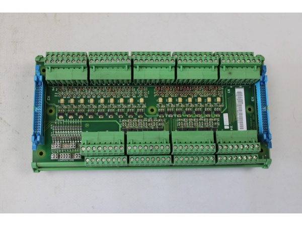
Hardware Architecture & Under-the-Hood Logic
The YPG109E module is designed as a high-precision analog input board that processes multiple analog signal channels for integration with ABB PLC and DCS control systems. It features analog signal conditioning circuitry, analog-to-digital converters, communication interfaces, and diagnostic capabilities to ensure accurate data acquisition and reliable system integration.
- Power is supplied to the module via DC 5V or variable voltage (100V-240V AC) depending on variant, which is regulated and distributed to internal circuits
- Analog signal conditioning circuitry processes incoming analog signals through:
- Input protection circuits for overvoltage and overcurrent protection
- Signal filtering and amplification for noise reduction
- Range scaling and offset adjustment for signal normalization
- Input impedance matching for minimal signal loading
- Multi-channel analog-to-digital conversion handles 8 channels (primary) or 4 channels (variant) through:
- High-resolution ADC (12-bit variant) for precise digital conversion
- Multiplexed channel scanning for efficient data acquisition
- Successive approximation or sigma-delta conversion techniques
- Calibration circuits for accuracy maintenance over temperature range
- Input signal support accommodates various analog signal types:
- Voltage signals: ±10V range with precision scaling
- Current signals: 4-20 mA with precision shunt resistors
- Differential or single-ended input configurations
- Programmable gain amplifiers for different input ranges
- Communication interfaces enable data exchange with control systems:
- DeviceNet protocol (variant) for industrial network integration
- Modbus RTU (related model reference) for serial communication
- Standard digital interfaces for PLC integration
- Diagnostic and status reporting channels
- Data processing and buffering capabilities manage acquired data:
- Data filtering and smoothing algorithms
- Linearization tables for non-linear sensor responses
- Data buffering for reliable transmission
- Event-driven data acquisition triggers
- Diagnostic and monitoring circuitry ensures reliable operation:
- Input channel fault detection (open circuit, overrange)
- Module health monitoring (temperature, supply voltage)
- Communication integrity checking
- Calibration status monitoring
- Anti-interference design for harsh industrial environments:
- Optical isolation for electrical noise immunity
- Shielded input traces for EMI protection
- Ground reference optimization for signal quality
- Multi-stage filtering for common-mode and differential noise
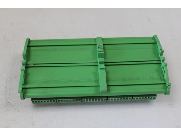
- Compact PCB design optimizes space utilization:
- High-density component layout for space efficiency
- Multi-layer PCB for signal integrity
- Thermal management for heat dissipation
- Mounting holes for standard rack installation
- Status indication via LED indicators provides diagnostic information:
- Power status LED
- Communication activity LED
- Channel status LEDs
- Fault indication LED
- Integration with ABB’s automation ecosystem through standardized interfaces and protocols
- Calibration and adjustment capabilities maintain accuracy over time:
- Software calibration routines
- Adjustable zero and span settings
- Temperature compensation algorithms
ABB YPG111A
Field Service Pitfalls: What Rookies Get Wrong
Incorrect Signal Range ConfigurationThe YPG109E supports multiple input signal ranges (±10V, 4-20 mA). Rookies sometimes configure the wrong range for their sensors, causing measurement errors or signal clipping.Field Rule: Always verify the sensor output range and configure the YPG109E input channels accordingly. Use the module’s configuration software to set the correct input type (voltage or current) and range. Never apply ±10V signals to a 4-20 mA configured channel or vice versa.
Improper Grounding of Analog InputsAnalog inputs require proper grounding to avoid ground loops and measurement errors. Rookies sometimes connect all analog signal grounds together indiscriminately, introducing noise and accuracy issues.Field Rule: Follow proper analog signal grounding practices. Use single-point grounding for analog inputs at the control system end. For floating signal sources, connect the signal return to the module’s designated analog ground reference. Avoid connecting shield wires at both ends to prevent ground loops.
Neglecting Input Signal FilteringIn industrial environments, analog signals often contain noise from nearby electrical equipment. Rookies sometimes install modules without proper signal filtering, leading to unstable measurements.Field Rule: Assess the signal quality during installation. If noise is present (observed on oscilloscope), implement appropriate filtering:
- RC low-pass filters on the sensor side
- Shielded twisted-pair cables for signal transmission
- Proper cable routing away from high-power conductors
- Module input filtering options if available
Overlooking Channel Calibration RequirementsHigh-precision analog measurements require periodic calibration. Rookies sometimes assume factory calibration remains valid indefinitely, leading to measurement drift over time.Field Rule: Establish a regular calibration schedule based on application criticality. For precision-critical applications, perform quarterly calibration. For less critical applications, annual calibration may suffice. Use calibrated reference sources (precision voltage sources, precision current sources) and follow the module’s calibration procedures. Document all calibration activities.
Incorrect Wiring of Differential vs. Single-Ended InputsThe module may support differential and single-ended input configurations. Rookies sometimes wire differential signals in single-ended mode, reducing noise immunity and measurement accuracy.Field Rule: Identify the input configuration requirements of your sensors and configure the module accordingly. For differential signals, use the designated positive and negative input terminals. For single-ended signals, connect the signal to the positive terminal and the signal return to the designated ground reference. Never mix differential and single-ended wiring without proper isolation.
Ignoring Temperature Effects on Measurement AccuracyThe module’s operating temperature range (-25°C to +60°C) affects measurement accuracy. Rookies sometimes install modules in locations experiencing temperature extremes without accounting for accuracy degradation.Field Rule: Install the YPG109E in locations within the specified operating temperature range. Avoid placing modules near heat sources (motors, drives, transformers) or in locations subject to cold drafts. For applications requiring high precision across temperature variations, implement temperature compensation or calibrate at the expected operating temperature.
Hot-Swapping Sensor ConnectionsSome technicians attempt to connect or disconnect sensor wiring while the system is powered, potentially damaging the module’s input circuits.Field Rule: Never hot-swap sensor connections. Power down the control system before connecting or disconnecting field devices. The module’s input circuits may not be designed for hot-swap and can be damaged by inrush currents or transient voltages during insertion/removal.
Overloading Input Channels with Excessive Signal LevelsApplying signals exceeding the configured input range (±10V) can damage input circuitry or cause permanent calibration errors. Rookies sometimes assume modules have built-in protection against overvoltage.Field Rule: Always verify sensor output signals are within the module’s input range before connection. Use voltage dividers or attenuators for signals exceeding ±10V. Implement external overvoltage protection (transient voltage suppressors, clamping diodes) in applications where sensor faults may produce excessive voltage.
Misinterpreting Diagnostic LED IndicationsThe module has status LEDs that provide valuable diagnostic information, but inexperienced technicians ignore them during troubleshooting.Field Rule: Learn to read the LED indicators:
- Power LED: Should be solid green when powered
- Communication LED: Blinks with DeviceNet/Modbus communication
- Channel Status LEDs: Illuminated when corresponding channel is active
- Fault/Error LED: Illuminates red on module faults, overrange conditions, or communication errors
Neglecting DeviceNet/Modbus Address ConfigurationIn multi-device networks, each module requires a unique communication address. Rookies sometimes duplicate addresses or fail to configure addresses at all, causing communication failures.Field Rule: Assign a unique DeviceNode ID or Modbus address to each YPG109E module on the network. Use the module’s address configuration switches or configuration software to set the address. Ensure no two devices share the same address. Document the assigned addresses for future reference and troubleshooting.
Improper Cable Selection for Analog SignalsUsing inappropriate cable types for analog signal transmission introduces noise and reduces measurement accuracy. Rookies sometimes use unshielded or underspecified cables to save costs.Field Rule: Use shielded twisted-pair cables designed for analog signal transmission. For 4-20 mA current signals, use cables with appropriate gauge to minimize voltage drop. For voltage signals, use cables with low capacitance to preserve signal integrity. Keep analog signal cables as short as practical and avoid running them parallel to power cables.
Failing to Isolate Unused Input ChannelsLeaving unused input channels open or unterminated can cause floating inputs and erratic readings or interference with active channels.Field Rule: Properly terminate unused input channels:
- For voltage inputs: short the positive and negative terminals together
- For current inputs: install a jumper across the input terminals or install a precision resistor
- Configure unused channels as disabled in the module’s configuration software if supported
Commercial Availability & Pricing Note
Please note: The listed price is for reference only and is not binding. Final pricing and terms are subject to negotiation based on current market conditions and availability. This product is part of ABB’s DCS Drive Series and Industrial Automation portfolio and may have different availability through various distribution channels depending on the specific variant and regional supply chain.


