
Description
Hard-Numbers: Technical Specifications
- Protocol Support: Modbus RTU slave, 4xxxx register area mapping for drive parameters and datasets
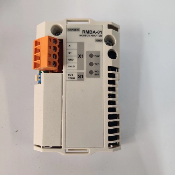
- Port Count: One 4-pin pluggable terminal block X1 (max 1.5 mm², shielded twisted-pair RS-485)
- Baud/Data Rate: 600, 1200, 2400, 4800, 9600, 19200 bit/s; some sources mention up to 115.2 kbps (verify with specific application/manual)
- Operating Temperature: Follows the drive hardware manual; separate data indicates –20°C to +60°C or –40°C to +85°C ranges (use final application requirements)
- Storage Temperature: –40°C to +85°C
- Isolation Rating: Galvanically isolated RS-485 interface (compliant with EN 50081-2 / EN 50082-2 EMC)
- Power Draw: Powered by RMIO at +5 V, max 140 mA (approx. 0.7 W); some sources list 1.5–5 W (use official manual as the final reference)
- Connectors: 38-pin parallel bus connector (plugged into RMIO); 4-pin terminal block X1 (A+, B–, GND, SHLD)
- Dimensions: Approx. 95 × 34 × 20 mm (refer to the official manual annex for exact figures)
- Weight: Approx. 0.06–0.5 kg (varies by packaging/kit)
- Control Modes: Modbus RTU slave; control sources are selectable via drive parameters (start/终止, reference, fault reset, etc.)
- I/O: No direct I/O on the adapter; interacts via the drive’s digital/analog I/O and Modbus registers
- Protection: IP20 (suits the drive environment)
- Topology/Bus: Multi-drop, max bus length 1200 m, max 31 stations per segment plus repeater; use twisted shielded cable (Belden 9841/9842 or equivalent recommended)
- Hardware Settings: 1 DIP switch S1 to enable/disable bus termination (ON/OFF)
- Supply: +5 V from RMIO board (auto-connected via the 38-pin connector during installation)
- Standards: EN 50081-2 (emissions), EN 50082-2 (immunity); UL/CSA-recognized materials
- Lifetime: Estimated minimum 100,000 hours (official manual annex)
- LED: 3 diagnostic LEDs (2 green: TxD/RxD; 1 yellow: STATUS)
- Registers: 4xxxx register area (maps drive parameters, status, and actual values; see register mapping table)

ABB RMBA-01
The Real-World Problem It Solves
ACS800/DCS800 drives need to connect to a Modbus network (e.g., for centralized monitoring and control by a Modicon PLC or host system). The RMBA-01 provides a galvanically isolated RS-485 interface, presenting the drive as a Modbus slave and supporting start/终止, speed/torque reference, process reference, status/actual value reading, parameter writes, and fault resets—all mapped to the transparent 4xxxx register area.
Where you’ll typically find it:
- Water treatment, HVAC, and other applications requiring Modbus remote monitoring and speed control
- OEM/system integration with Modicon PLCs or other Modbus masters
- Production lines and process control where multiple drives need centralized management via Modbus
Bottom-line: It bridges drives to Modbus networks, enabling PLCs or hosts to transparently read/write and control drives via a standardized register map.
Hardware Architecture & Under-the-Hood Logic
RMBA-01 is an optional fieldbus adapter that inserts into RMIO board SLOT 1 (it can also be mounted externally to an AIMA-01). The module auto-connects signals and power via a 38-pin connector; a 4-pin terminal block X1 connects the shielded twisted RS-485 cable. Internally, it provides galvanic isolation, a built-in termination resistor, and operates as a Modbus RTU slave responding to the bus.
-
Register mapping and the 4xxxx area: The drive emulates a Modicon PLC 4xxxx (holding register) area; drive parameters and datasets are mapped there. An external host can read/write this register area for parameter readout, changes, reference commands, and status fetching. Detailed mapping follows the table (register address = 4GGPP, where GG is the parameter group and PP is the parameter within the group).
-
RS-485 galvanic isolation and termination: The module provides a galvanically isolated RS-485 interface to reduce ground loops and common-mode disturbances. An integrated active termination resistor (120 Ω) can be enabled via DIP switch S1; enable termination only at the end(s) of the bus.
-
Communication rate and topology: Supports common Modbus RTU baud rates; maximum bus length 1200 m using multi-drop topology; use twisted shielded cable (Belden 9841/9842 or equivalent recommended).
-
Diagnostic LEDs: Two green LEDs (TxD, RxD) indicate transmit/receive; one yellow STATUS LED indicates module status; use these for communication and troubleshooting.
-
Control source selection: In drive parameters, select “communication module” as the source for start/终止, reference, and fault reset; otherwise, Modbus commands will not take effect.
-
Broadcast write: The adapter supports Modbus broadcast writes (master writes to all slaves simultaneously). Broadcast writes return no acknowledgment; ensure data consistency when used.
-
Exception codes and data updates: Communication failures or out-of-range parameters return exception codes (e.g., ILLEGAL DATA VALUE). Data update timing is optimized for reliability.
ABB RMBA-01
Field Service Pitfalls: What Rookies Get Wrong
-
Incorrect bus termination switch: Enable termination only at the bus ends; otherwise, reflections cause communication instability. Verify ~120 Ω between A–B with a multimeter when terminated.
-
Not enabling the communication module in drive parameters: If “control panel” or another source is selected, Modbus control commands (start/终止, reference) will not execute. Set drive parameters to use “communication module” as the control source.
-
Skipping version compatibility check: RMBA-01 is compatible with ACS800 Standard Application Program version ASXR7000 or later; older firmware may lead to non-recognition or communication failures.
-
Overloading or damaging the termination: Enabling termination at internal nodes or at multiple nodes causes abnormal bus impedance and unstable communication. Enable termination only at the two end nodes.
-
Improper shield grounding: Ground the Modbus cable shield at a single point only; multi-point grounding creates ground loops and noise. Follow the recommended wiring and grounding practices.
-
Electrical isolation and common-mode voltage: While RS-485 isolation tolerates some common-mode voltage, keep cables spaced from power/motor cables and route them properly to reduce induction and crosstalk.
-
Incorrect register addresses and parameter mapping: Parameter read/write register addresses follow 4GGPP (GG = parameter group, PP = parameter within the group). Mapping can vary slightly by drive series/firmware; always consult the latest register mapping table.
-
Using the wrong cable or baud rate: Use shielded twisted-pair RS-485 (Belden 9841/9842 or equivalent). Ensure baud rate matches the PLC/host; mismatches prevent communication.
-
Ignoring LEDs and physical connections during faults: For communication issues, first observe LEDs and check terminal X1 wiring, RMIO mounting/grounding (the two screws provide both fixing and grounding), then verify drive parameters and the Modbus master program.
Commercial Availability & Pricing Note
- Important note: Listed prices are for reference only and are not binding. Final prices and terms depend on market conditions, availability, and negotiation.
- Component/Kit: RMBA-01-KIT often ships as a kit (with installation accessories); RMBA-01 can be a standalone module. Confirm the exact contents and version with your supplier before ordering.
- Substitution/upgrade: Some sources mark this item as OBSOLETE. To avoid unplanned downtime, discuss repair or alternative solutions with your supplier.


