
Description
Hard-Numbers: Technical Specifications
Actuator Specifications
- Rated Torque: 250 Nm (185 lbf·ft), electrically adjustable to 50%, 75%, or 100%
- Starting Torque: 1.2 × rated torque (break-away torque in end positions: 2 × rated torque for short duration)
- Rated Operating Speed: 9.0 to 0.1°/s (adjustable via electronic unit)
- Rated Time for 90°: 10 to 900 seconds (adjustable)
- Operating Angle: Typically 90° (minimum 35°, maximum 140° with lever and limit stops)
- Motor Type: BD 80M1-4B, three-phase asynchronous motor with flameproof enclosure
- Brake: Spring-loaded brake, energized in automatic mode, maintenance-free
- Weight: 61.5 kg (136 lb)
- Protection Class: IP66
- Explosion Protection: ATEX II 2 GD ck EEx de [ib] ib II B T4 (Ex zones 1 and 21)
Environmental Conditions
- Ambient Temperature (Standard): -25°C to +60°C (-13°F to +140°F)
- Ambient Temperature (Extended): -30°C to +40°C (-22°F to +104°F)
- Operating Speed Reduction: Below -10°C (14°F) at rated load
- Transport/Storage Temperature: -30°C to +60°C (-22°F to +140°F)
- Long-term Storage Temperature: -30°C to +40°C (-22°F to +104°F)
- Humidity: 95% annual average (condensation not permitted)
- Corrosion Protection: C5-I category (highly polluted industrial atmospheres), DIN EN 15714 compliant
- Coating: 2-layer epoxy resin (RAL 9005, black)
Power Supply
- Supply Voltage: 115 V AC (94 to 130 V) or 230 V AC (190 to 260 V)
- Frequency: 47.5 to 63 Hz, single-phase
- Maximum Current: 1.8 A at 115 V, 0.9 A at 230 V
- Positioning Current Draw: Approximately 40-50% of Imax
- External Fuse: 16 A, time-lag type
- Power Source: Via Contrac electronic unit only (EBN853 for field mounting, EBS852 for rack installation)
Communication Interfaces
- Analog Input: 0/4 to 20 mA, internal load 300 Ω
- Analog Output: 0/4 to 20 mA, electrically isolated, max. load 500 Ω
- Digital Inputs: 3 inputs (Digital 0: -3 to 5 V or open; Digital 1: 12 to 35 V), electrically isolated
- Digital Outputs: 3 outputs, potential-free relay contact, max. 60 V, 150 mA
- Digital Communication: RS232 for commissioning and service
- Fieldbus Protocols: PROFIBUS DP®/DP®V1 or HART® communication (optional)
- Voltage Output: +24 V, 15 mA, electrically isolated (for external contacts/scanning)
- Transmitter Supply: Two-wire transmitter with activated process controller (optional)
Mechanical Specifications
- Gear Type: Oil-lubricated spur gearing
- Position Sensor: Mounted directly on rear end of output drive shaft (backlash-free feedback)
- Mechanical Limit Stops: Adjustable, located on outside of gear case
- Handwheel: Differential gearing design, accessible at any time without interrupting gear train
- Mounting Position: IMB3, IMB6, IMB7, IMV6 (preferably IMB3 per EN 60034-7)
- Connection Pipe: 1¼ in DIN EN 10255 / ISO 65 or 1¼ in schedule 80 pipe (not included)
- Ball/Socket Joint Deflection: Max. 3° toward actuator, max. 10° away from actuator

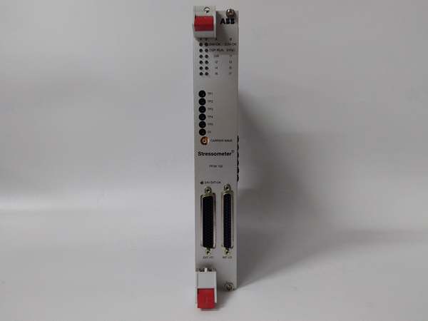
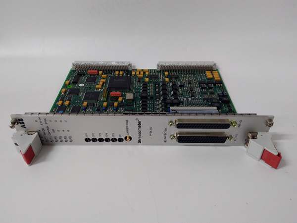
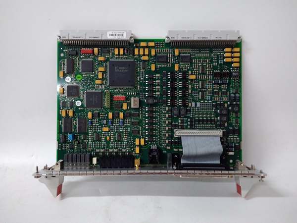
ABB PFSK152 3BSE018877R1
The Real-World Problem It Solves
Process industries need precise valve control in explosive environments where pneumatic actuators can’t maintain stable positioning under varying process conditions, and traditional electric actuators overheat or fail in continuous modulation duty. The RHD250-10 eliminates this gap with S9 stall-proof design that runs continuously at 100% duty cycle without temperature derating, delivering 250 Nm of precise torque control through ATEX-certified explosion protection.
Where you’ll typically find it:
- Oil and gas pipeline valve stations requiring Ex-proof modulating control
- Chemical plant reactor feed and temperature control loops in Zone 1 hazardous areas
- Power plant damper control for combustion air regulation with explosion protection requirements
- Pharmaceutical manufacturing process control valves requiring Class II Division 1 compliance
This actuator reduces maintenance intervals to 10 years under normal load, eliminates position-dependent shut-off failures common in conventional actuators, and provides continuous modulating precision without the air supply infrastructure required by pneumatic systems.
Hardware Architecture & Under-the-Hood Logic
The RHD250-10 operates on the Contrac continuous positioning principle, where the electronic unit varies motor torque steplessly until actuator force equals valve process force. The three-phase asynchronous motor remains permanently energized under voltage, with the electronic unit adjusting torque in proportion to the ΔY signal (difference between set point and position signal).
Internal Signal Flow:
- Set point signal (4-20 mA or digital bus command) enters Contrac electronic unit (EBN853/EBS852)
- Electronic unit calculates ΔY error between set point and actual position feedback
- Motor controller adjusts three-phase motor voltage to vary torque proportionally to error signal
- Motor drives oil-lubricated spur gearing to rotate output shaft
- Position sensor on output shaft provides backlash-free position feedback to electronic unit
- Spring-loaded brake remains energized (released) during automatic operation for Fail-Freeze action
- At balance point, actuator force equals process force, holding valve in required position
- Mechanical limit stops absorb torque peaks in end positions for travel path limitation
- In fault or power loss condition, spring engages brake via de-energization, locking valve in current position
- External communication (PROFIBUS/HART) allows parameterization and diagnostics without interrupting operation
S9 Stall-Proof Operation:Unlike conventional actuators that cycle on/off to maintain position, the RHD250-10 motor runs continuously at variable torque, eliminating thermal cycling stress. This enables Class D continuous modulation operation per EN 15714-2 with 10-year maintenance intervals.
ABB PFSK152 3BSE018877R1
Field Service Pitfalls: What Rookies Get Wrong
Missing Motor Temperature Monitoring in Ex Zones
Techs install the RHDE250-10 in hazardous areas (Zone 1/21) and connect it to the electronic unit without installing the required ABB SD241-B monitoring unit or comparable certified thermistor tripping device. The motor overheats in continuous modulation duty because the internal thermal protection isn’t monitored independently as required by ATEX standards.
Field Rule: In explosive atmosphere installations, you must install an ABB SD241-B motor temperature monitoring unit (or equivalent certified device) that interrupts power when motor temperature exceeds the permissible limit. Connect the thermistor leads from the motor to the monitoring unit, then wire the monitoring unit contact into the power feed to the electronic unit. This is mandatory ATEX compliance—skip it, and your installation fails certification.
Improper Shield Grounding in Ex Applications
Rookies run shielded cables for motor, sensor, and signal connections but leave the shields unconnected or ground only one end. In Ex areas with increased safety (Ex e) requirements, this creates EMI issues and violates installation codes. The floating shields pick up noise from nearby power equipment, causing erratic valve movement or false position feedback.
Quick Fix: Connect the cable shielding on both ends (actuator side and electronic unit side) and bond to protective ground (PE) using the shield terminals provided. For motor and sensor cables, ensure shield continuity through the Ex e cable glands. Use Ex-certified cable glands that ensure proper shield contact. Do NOT leave shields floating in any Ex zone installation.
Ignoring Reduced Speed Below -10°C
Techs commission actuators in cold climates during summer, then when winter arrives and ambient temperatures drop below -10°C (14°F), the actuator slows down dramatically because the electronics reduce operating speed at rated load. Operators complain about sluggish response during cold startups, assuming the actuator is failing.
Field Rule: The RHD250-10 automatically reduces operating speed at rated load when ambient temperature falls below -10°C (14°F). This is normal derating behavior, not a fault. For cold climate applications, specify the extended temperature range option (-30°C to +40°C) during ordering, or adjust your control loop tuning to account for slower response at low temperatures. Don’t disable this protection—the electronics are protecting the motor from cold-start overload.
Mixing Up Lever Mounting Orientation
The lever assembly connects to the output shaft via keyway, but techs install it backwards or at the wrong angle, causing the ball-and-socket joints to bind during rotation. The actuator struggles against the mechanical restriction, drawing excess current and overheating the motor while the valve never reaches full travel.
Quick Fix: Verify lever orientation marks align with the actuator mounting position. The lever set includes two ball-and-socket joints—ensure the joints can articulate through their full deflection range (3° toward actuator, 10° away from actuator) without binding. Install the connecting pipe at the correct length per your valve stem-to-actuator shaft dimension (1¼ in schedule 80 pipe, not included). Test full travel range by handwheel operation before applying power.
Forgetting to Configure Digital Input Priorities
The Contrac electronic unit defaults digital inputs to specific functions (DI1: manual/auto switching, DI2/DI3: travel commands), but techs wire them as simple open/close commands without configuring priorities in the software. When a digital input activates, it takes priority over the set point signal, so unexpected manual commands override automatic control from the DCS, causing process upsets.
Field Rule: Always configure the digital input functions using the Contrac interface software (Asset Vision Basic with DTM400 or EDD) to match your control philosophy. If you’re using digital inputs as supplemental open/close commands, set them to the “Travel command in OPEN/CLOSE direction” configuration and verify that DI1 (manual/auto switching) is properly wired if you need local override capability. The default settings assume DI1 is the manual/auto selector—don’t leave it floating or it will randomly switch modes.
Overlooking Torque Adjustment for Valve Size
Techs install a 250 Nm actuator on a valve that only needs 150 Nm of torque and leave the setting at 100% (250 Nm). The oversized actuator delivers excessive force, damaging valve seats and seals over time. Conversely, they might under-torque a large valve, causing the actuator to stall in end positions while drawing excessive current.
Quick Fix: Adjust the nominal torque setting to match your valve requirements via the electronic unit parameterization. Available settings are 50%, 75%, or 100% of the 250 Nm rated output. Start at 75% and verify the valve opens and closes smoothly, then adjust up only if necessary. Proper torque matching extends valve seat life and reduces actuator wear—don’t default to maximum unless your application specifically requires it.
Commercial Availability & Pricing Note
Please note: The listed price is for reference only and is not binding. Final pricing and terms are subject to negotiation based on current market conditions and availability. RHDE250-10 units are typically configured as explosion-proof assemblies with associated electronic units (EBN853 or EBS852) ordered separately. Lead times vary based on temperature range option and explosion protection certification requirements.


