
Description
Key Technical Specifications
-
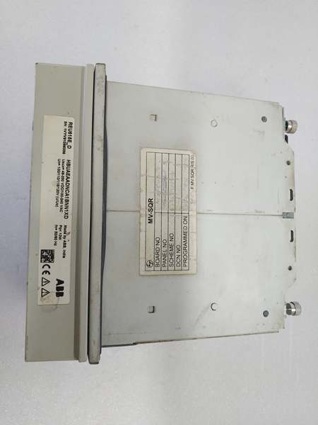
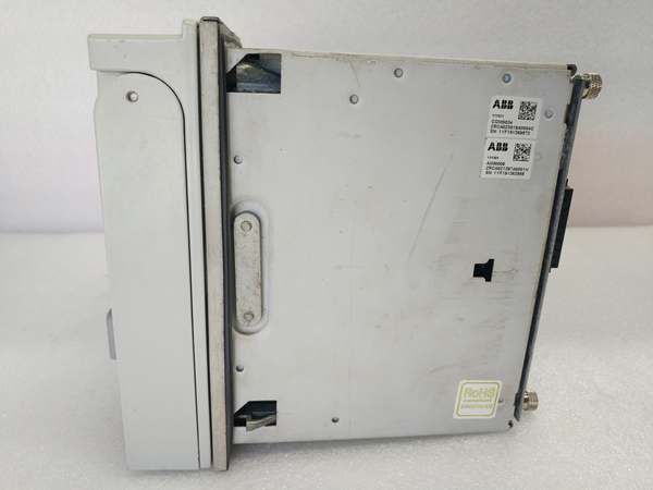
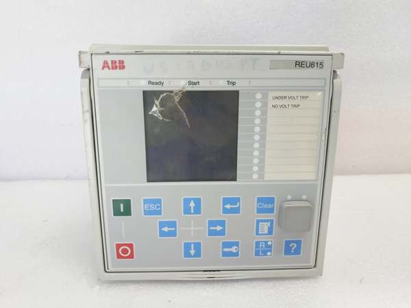
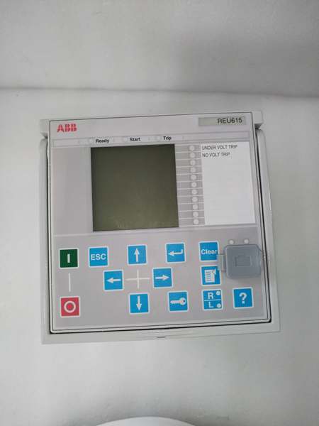
Model Number: REU615
-
Manufacturer: ABB
-
Protection Functions: 27/59/27R/81O/U/81R/47/60FL/60V/67N/50BF/49F/50/51/50N/51N/67/32R/40/46/21/25/79/74T/50LC/60CT/60VT
-
Voltage Inputs: 60–210 V AC (1- or 5- A current inputs)
-
Frequency Tracking: 45–65 Hz (±5 Hz); 0.5–500 Hz measurement
-
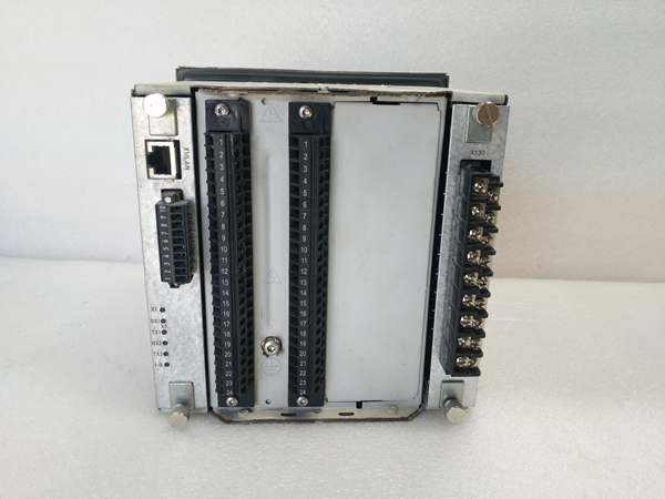
On-board COM: 2 × RJ-45 100BASE-TX (HSR/PRP), 1 × RS-232/485
-
Protocols: IEC 618-50-8-1 & 9-2LE, GOOSE, Modbus-TCP/RTU, DNP3, IEC 60870-5-103
-
Time Sync: IEEE 1588 v2 (1 µs accuracy), IRIG-B optional
-
OLTC Outputs: 6 × BO (250 V, 8 A), configurable pulse / maintained
-
Auxiliary Supply: 48–250 V DC / 100–240 V AC, < 18 W max
-
Operating Temp: –25 °C…+55 °C continuous; –40 °C…+85 °C transport
-
Housing: 4U × 177 mm withdrawable plug-in, IP 54 front, IP 20 rear
- Weight: 4.1 kg complete; 2.1 kg module only

ABB REU615
Field Application & Problem Solved
Plants that run motor-driven on-load tap changers hate hunting voltage by hand. A 5 MVA step-down sitting at the end of a long 34.5 kV feeder can drift ±5 % every shift because the PF correction caps kick in and out. Hang a REU615 in the breaker cell, land one VT set on the bus, one on the load, and tell it the center voltage you want (say 13.2 kV). The relay watches both magnitude and phase angle, issues raise/lower pulses, and blocks when the LTC hits end-tap or when the volts collapse during a downstream fault. Net result: voltage held inside 1 % band, no operator touches the handle for months. I’ve used the same box for under-frequency load shedding in a paper-mill cogen house—one GOOSE message trips the wood-room chippers before the turbine falls below 59 Hz, saving the island. Dual HSR ports mean you lose one fiber and the IEC-61850 messages still stream; mill electricians love not having to explain “switchover time” to the shift boss.
Plants that run motor-driven on-load tap changers hate hunting voltage by hand. A 5 MVA step-down sitting at the end of a long 34.5 kV feeder can drift ±5 % every shift because the PF correction caps kick in and out. Hang a REU615 in the breaker cell, land one VT set on the bus, one on the load, and tell it the center voltage you want (say 13.2 kV). The relay watches both magnitude and phase angle, issues raise/lower pulses, and blocks when the LTC hits end-tap or when the volts collapse during a downstream fault. Net result: voltage held inside 1 % band, no operator touches the handle for months. I’ve used the same box for under-frequency load shedding in a paper-mill cogen house—one GOOSE message trips the wood-room chippers before the turbine falls below 59 Hz, saving the island. Dual HSR ports mean you lose one fiber and the IEC-61850 messages still stream; mill electricians love not having to explain “switchover time” to the shift boss.
Installation & Maintenance Pitfalls (Expert Tips)
VT Polarity Kills Regulation – If the line-side VT is 180° out, the relay thinks load volts are high and drives the tap changer down until you bottom out. Check phasor diagram with the built-in synchro-check before you close the control enable.
OLTC Pulse Too Short – Factory default is 500 ms; many LTCs in the field need 1–1.5 s to complete a step. Short pulses make the drive clutch slip and burn carbon brushes. Bump LCT_PULSE_TIME until you hear one clean “clunk” per command.
Forget Line-Drop Compensation? – A 4 % drop on the feeder makes the relay hold 12.7 kV at the bus while customers see 12.2 kV. Enable LDC, enter your R + X values from the cable book, or you’ll get “low-voltage” complaints even though the relay is green.
1588 Grandmaster Missing – Without PTP the event log time-stamps drift; after a fault you’ll never line up relay data with the SCADA historian. If the plant LAN doesn’t run 1588, strap IRIG-B to X100 and be done.
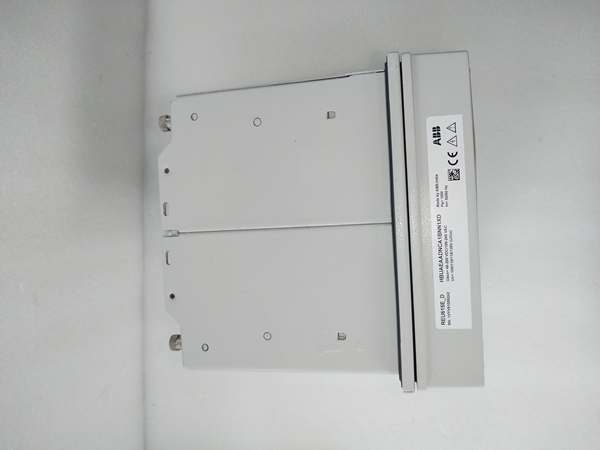
ABB REU615
Technical Deep Dive & Overview
REU615 is basically a 615-series hardware shell built around two DSP cores: one handles protection algorithms, the second runs the OLTC state machine and GOOSE publisher. Sample rate is 1 kHz on voltage and current; the ADCs feed a 32-point cosine filter that gives < 0.5 % V accuracy down to 5 % nominal. The regulation loop uses a PI controller with user-set bandwidth (1.2–18 %) and stability factor; it can track load current phase angle to compensate for reactive drop. Communication rides on a shared 100 Mb switch fabric—HSR frames are duplicated and forwarded out both ports, PRP frames are stamped LAN-A / LAN-B, so either fiber can fail with zero re-convergence. All settings live in a single .pcmi file; swap the module and the relay pushes the config from the rear carrier EEPROM—no laptop on the front panel unless you like standing in front of 4 kV switchgear at 2 a.m.
REU615 is basically a 615-series hardware shell built around two DSP cores: one handles protection algorithms, the second runs the OLTC state machine and GOOSE publisher. Sample rate is 1 kHz on voltage and current; the ADCs feed a 32-point cosine filter that gives < 0.5 % V accuracy down to 5 % nominal. The regulation loop uses a PI controller with user-set bandwidth (1.2–18 %) and stability factor; it can track load current phase angle to compensate for reactive drop. Communication rides on a shared 100 Mb switch fabric—HSR frames are duplicated and forwarded out both ports, PRP frames are stamped LAN-A / LAN-B, so either fiber can fail with zero re-convergence. All settings live in a single .pcmi file; swap the module and the relay pushes the config from the rear carrier EEPROM—no laptop on the front panel unless you like standing in front of 4 kV switchgear at 2 a.m.


