Description
Product Core Brief
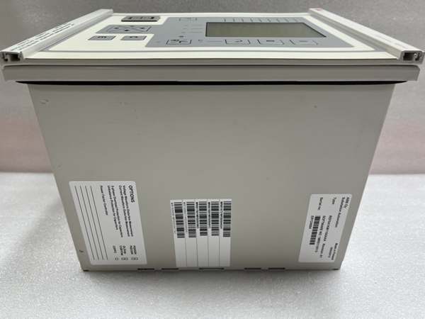
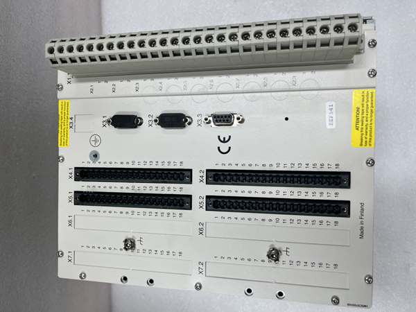
- Model: REF541KM118AAAA
- Brand: ABB
- Series: REF541 Medium Voltage Feeder Terminal
- Core Function: All-in-one relay executing MV feeder protection, breaker control, power measurement, fault recording and substation automation logic for distribution networksABB Group.
- Product Type: Multi-Functional Medium Voltage Feeder Protection Relay
- Key Specs: 15 Digital Inputs | 12 Trip/Control Output Relays | SPA/LON/IEC 60870-5-103 native bus
- Note: Official end-of-production since 2022; limited residual factory new stock and fully bench-tested surplus available for legacy substation maintenanceABB Group.
Key Technical Specifications
| Parameter | Value |
|---|---|
| Full Order Code | |
| Auxiliary Supply Range | PS1 module: 80–265 V AC/DC; max 30 W power draw |
| CT Rated Input | 1 A / 5 A selectable secondary current |
| VT Rated Input | 100 V phase-to-phase voltage transformer input |
| Analog Measuring Channels | 9 galvanically isolated CT/VT signal channels |
| Digital Inputs | 15 galvanically isolated binary status inputs |
| Output Relays | 12 isolated power outputs (high-speed trip + control breaker contacts) |
| Onboard Communication | SPA bus, LON bus, IEC 60870-5-103; IEC 61850 via SPA-ZC400 adapter |
| Built-In Protection Function Set | Non-directional overcurrent (51), earth fault (51N), thermal overload (49), undervoltage (27), overvoltage (59), synchro-check (25), phase unbalance, fault locator |
| Logic Capacity | IEC 61131-3 integrated PLC sequence logic for bay automation |
| Event Storage | 100 timestamped fault/operational event records non-volatile flash storage |
| Backup Clock Supply | 48-hour capacitor backup for real-time clock during auxiliary power loss |
| Operating Ambient Temp | -10 °C to +55 °C panel-mounted |
| Storage Temperature Range | -40 °C to +70 °C |
| Enclosure Protection | Front IP54 flush mount; rear terminal section IP20 |
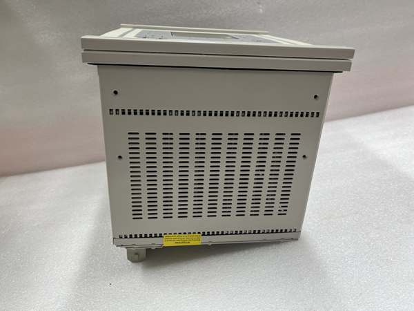
| Mechanical Form Factor | 6U 19-inch half-rack panel mount |
| Physical Dimensions | 223.7 mm W × 265.9 mm H × 235 mm D |
| Unit Weight | ~8 kg full assembly |
| Compliance Standards | IEC 60255, IEC 61131-3, IEC 61850, UL508 |
Product Introduction
This feeder terminal consolidates protection, control, metering and bay automation into a single panel-mounted unit for 3–36 kV distribution feeders, shunt capacitor banks and medium-sized asynchronous motorsABB Group. It supports isolated, resonant-earthed and solidly earthed grid neutral configurations without hardware modification.
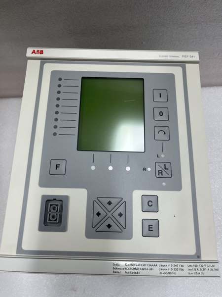
The multiprocessor DSP architecture delivers consistent sub-85ms trip latency for short-circuit faults, while the configurable LCD mimic panel displays single-line bay diagrams, live analog values and fault diagnostics without external SCADA access. Embedded PLC logic eliminates separate auxiliary relay racks for interlocking and automatic reclosing sequences.
QA & Testing SOP (Transparency Building)
- Incoming Inspection: Cross-reference full model code against OEM spare registry to reject counterfeit hardware; inspect LCD panel, relay terminal screw blocks and internal PCB conformal coating for scratches, discoloration or water residue; log serial numbers and production batch codes for full traceability.
- Live Testing: Mount unit to standard 19-inch test rack, supply regulated 220 VAC/DC auxiliary power, inject simulated CT/VT analog signals, run continuous 24-hour protection element cycling and SPA/LON bus communication stress testing with fault event logging validation.
- Electrical Testing: Use Fluke 115 multimeter and insulation tester to verify chassis ground resistance below 0.5Ω and isolation resistance above 10MΩ between power, analog and digital circuits.
- Firmware/Config Backup: Record exact embedded firmware revision via Relay Setting Tool, photograph front panel DIP communication address switches, export complete protection setting groups and PLC logic to encrypted offline storage.
- Final QC & Packaging: Clean LCD surface with anti-static microfiber cloth, cover terminal blocks with insulating caps, seal unit inside ESD shielding bag, attach printed QC test tag with technician ID and full test runtime timestamp before foam-lined transit carton packaging.
Installation Pitfalls & Guide (Engineer to Engineer)
❗ Firmware Version Mismatch: Firmware builds newer than site Relay Setting Tool software block full PLC logic upload and disable fault locator calculation; cross-check OEM software compatibility matrix before downloading parameter sets.❗ CT Open-Circuit Hazards: Disconnecting current transformer wiring while the unit remains energized generates dangerous high secondary voltage; short CT terminals before disassembly per substation safety protocols.❗ LON/SPA Bus Address Conflicts: Duplicate bay node addressing floods substation communication bus with broadcast traffic; capture high-resolution photos of original front-panel DIP switch layout prior to removal.❗ Auxiliary Supply Underrating: The unit draws peak 30 W during full relay output actuation; shared cabinet DC power supplies with multiple protection relays trigger voltage sag and incomplete relay boot sequences.❗ ESD Dangers: Unwristed technician contact with rear exposed PCB traces corrupts flash-based protection settings and clock backup circuits; field service logs show ungrounded handling destroyed this terminal with over $4,800 in hardware and substation outage labor costs.
4-step replacement guide:
- Pre-install: Lock out and tag out substation auxiliary supply, short all CT secondary wiring, fit certified anti-static wrist strap, photograph analog CT/VT wiring, digital input/output terminal routing and communication bus DIP switch positions.
- Removal: Unfasten rear terminal screw blocks, disconnect SPA/LON communication cables, release front panel mounting latches, slide the unit forward out of the 6U rack cutout.
- Install: Seat new unit flush to panel frame, lock mounting latches, replicate original DIP communication address settings, reterminate all CT/VT, DI/DO and bus wiring, remove CT shorting jumpers.
- Power-on Test: Restore auxiliary supply power, upload matching firmware and protection setting groups, inject simulated fault signals to validate trip element operation, confirm event logging and stable SCADA communication via SPA bus.
FAQ (Frequently Asked Questions)
Q: Can directly replace REF543 or REF545 series terminals without full rework?A: Mechanical rack form factor matches, but the unit has fewer I/O channels and limited expansion slots compared to REF543/REF545. Drop-in swap requires reconfiguring all protection logic and adjusting SCADA point mapping to account for missing analog/digital channels.Q: Does the feeder terminal support hot-swapping while the substation auxiliary bus remains energized?A: Hot-swapping is fully unsupported. Removing the unit mid-operation opens CT circuits and disconnects bay control interlocks, creating safety hazards and uncontrolled breaker state transitions; full auxiliary power lockout is mandatory for replacement.Q: What warranty coverage applies to stocked hardware?A: Remaining factory-new OEM legacy spares carry a 12-month manufacturer warranty covering all measurement, protection and communication circuits. Bench-tested surplus inventory ships with a 6-month functional warranty; physical damage from miswiring, CT open-circuit transients or ESD voids all coverage terms.Q: Has ABB issued formal EOL documentation for this model?A: End-of-production status active since 2022; OEM no longer manufactures new batches, only limited residual surplus stock exists for legacy distribution substation fleets. Verify with OEM datasheet for modern REF615/REF620 protection relay upgrade alternatives.Q: Will protection setting groups and PLC automation logic persist after swapping the terminal?A: All trip curves, fault thresholds and bay control logic reside in internal flash memory, not the grid wiring. Back up the full project database from the old unit before removal and re-download to the new terminal post-install; firmware mismatches corrupt setting upload sequences.Q: What communication adapters are compatible with the native SPA bus port?A: Valid expansion adapters include SPA-ZC400 (IEC 61850 Ethernet), SPA-ZC302 (Profibus DP V1) and SPA-ZC200 (Modbus RTU). Cross-reference the REF54 series hardware manual for maximum substation bus node limits.Q: Can this unit be deployed for high-voltage transmission line protection?A: Native protection algorithms are calibrated exclusively for medium voltage distribution feeders, capacitors and motors. The fault locator and overcurrent element resolution do not meet HV transmission line protection requirements; ABB recommends REF630 series relays for transmission applications.