

Description
Hard-Numbers: Technical Specifications
- Protocol Support: DDCS (fiber optic), Modbus RTU, PROFIBUS DP, PROFINET, Ethernet/IP (via optional adapters)
- Port Count: 7 digital inputs, 3 relay outputs, 3 analog inputs, 2 analog outputs, 1 reference voltage output
- Baud/Data Rate: 10 MBd PPCS fiber link to power unit
- Operating Temperature: 0°C to +60°C (ambient), -40°C to +70°C (storage)
- Isolation Rating: 500 VAC analog/digital group isolation, 4 kVAC relay output isolation
- Power Draw: 24 V DC ±10%, typical 250 mA, maximum 1.2 A (with option modules)
- Processor: Embedded DSP with DTC algorithm
- I/O Specifications:
- Analog Inputs: 3 differential inputs (1 voltage ±10V, 2 current 0/4-20mA), 12-bit resolution
- Analog Outputs: 2 current outputs 0(4)-20mA, 10-bit resolution
- Digital Inputs: 6 programmable DI + 1 start interlock, 24 V DC, 1 ms filter
- Relay Outputs: 3 changeover contacts, 8 A @ 24 V DC / 250 V AC, 2 A max continuous
- Dimensions: 127mm x 25mm x 279mm (5.0″ x 1.0″ x 11.0″)
- Weight: 0.5-0.6 kg (1.1-1.3 lbs)
- Control Modes: DTC (Direct Torque Control), V/f control, Scalar
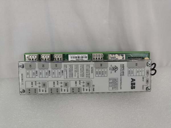
- Expansion Slots: Slot 1 (X31) and Slot 2 (X32) for I/O extension, encoder interface, or fieldbus adapters
- Communication Interface: DDCS port (X33) for RDCO modules, RS-485 for control panel

ABB RDCU-12C
The Real-World Problem It Solves
ACS800/ACS880 drives need a central control unit that processes motor currents, executes torque/speed control algorithms, manages I/O signals, and communicates with external control systems. The RDCU-12C integrates these functions into a single replaceable module, enabling high-performance motor control without encoder feedback and providing expandable I/O and fieldbus connectivity.
Where you’ll typically find it:
- Water treatment plant pump stations requiring PID flow control and PROFIBUS DP integration
- Steel rolling mills needing precise torque control for material forming processes
- Paper machines with multiple drive sections requiring coordinated speed control via master/follower links
- Mining hoist systems with high dynamic torque demands and safety interlock requirements
Bottom-line: It’s the brain of ACS800 drives, delivering DTC sensorless vector control that provides encoder-level performance while reducing system complexity and cost.
Hardware Architecture & Under-the-Hood Logic
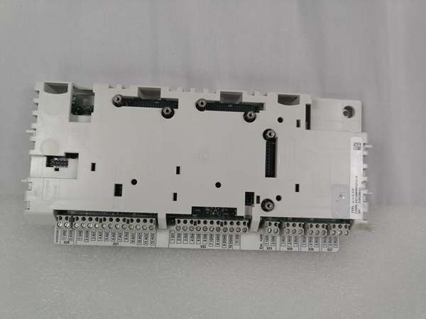
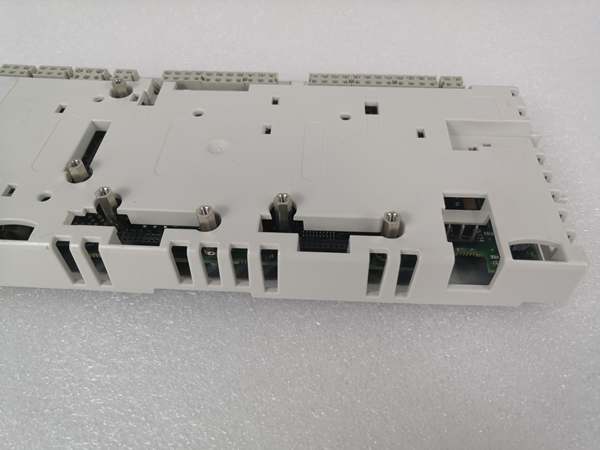
The RDCU-12C consists of the RMIO-12C Motor Control and I/O board integrated into a plug-in control unit. The board contains the main processor executing DTC algorithm, analog/digital signal conditioning circuits, relay drivers, and communication interfaces.
- DTC Torque Calculation: The DSP samples motor current and voltage at high frequency (typically 40,000 times/second) to calculate stator flux and torque in real-time without requiring encoder feedback.
- Analog Input Processing: Three differential analog inputs with programmable ranges (±10V or 0/4-20mA) provide reference signals and feedback measurements. Inputs are galvanically isolated as a group with 500 VAC test voltage.
- Digital Input Filtering: Six programmable digital inputs with 24 V DC logic levels feature 1 ms hardware filtering to debounce noisy signals from field devices. Inputs can be split into two isolated groups via jumper J1.
- Relay Output Driving: Three relay outputs with changeover contacts support AC or DC loads up to 250 V AC or 24 V DC at 8 A switching capacity. Outputs are isolated with 4 kVAC test voltage.
- PPCS Fiber Communication: The board communicates with the power stage through 10 MBd optical fiber links (V57, V68) using ABB’s PPCS protocol, ensuring electrical isolation and noise immunity.
- Expansion Slot Architecture: Two 38-pin expansion slots (X31, X32) support I/O extension modules (RAIO, RDIO), pulse encoder interfaces (RTAC), and fieldbus adapters (RPBA for PROFIBUS, RMBA for Modbus).
- DDCS Communication Port: A dedicated 20-pin header (X33) connects RDCO fiber optic communication modules for fieldbus adapter linking, master/follower applications, and PC tool connections.
- Power Management: The unit is powered by 24 V DC through connector X34. Internal regulation provides +5 V for logic and ±10 V reference for analog circuits. Maximum current draw is 1.2 A when fully equipped with option modules.
ABB RDCU-12C
Field Service Pitfalls: What Rookies Get Wrong
Replacing RDCU Without Transferring Application Software
Technicians swap out a faulty RDCU-12C with a blank replacement board and expect it to work immediately. The new board has no application software loaded (ASxR, AMXR, or AHxR programs), causing the drive to fail initialization or operate with default parameters unsuitable for the application.
Quick Fix: Always back up the application software from the faulty board using DriveWindow or DrivePC software before removal. Order the correct software package (ASxR for standard applications, AMXR for system applications, AHXR for pump/fan control) or purchase a pre-programmed board (3AUA0000036521P). Load the software and parameters onto the replacement board before commissioning.
Incorrect Jumper J1 Configuration
Engineers leave jumper J1 in default position (all digital inputs share common ground) when the application requires isolated input groups. This causes ground loops between field devices, resulting in erratic digital input behavior and intermittent drive faults.
Field Rule: Verify the application requirements for digital input isolation before installation. If the field devices have separate ground references, configure jumper J1 to split grounds (DI1-DI4 isolated from DI5/DI6/DIIL). Set the jumper before mounting the board—changing it after installation requires removing the board cover.
Overloading Relay Outputs with Inductive Loads
New techs connect inductive loads like contactor coils or solenoid valves directly to relay outputs without surge suppression. The inductive kickback causes contact arcing, welds relay contacts together, and eventually destroys the relay outputs.
Quick Fix: Always install RC snubber circuits (typically 100Ω resistor + 0.1µF capacitor) across inductive loads connected to relay outputs. For DC coils, use flyback diodes (1N4007 or equivalent) rated for the coil current. Never exceed 2 A continuous current rating per relay output.
Ignoring Option Module Current Limits
Engineers populate both expansion slots (X31, X32) with option modules without calculating total current draw. The RDCU-12C maximum current consumption is 1.2 A with option modules. Exceeding this causes unstable 24 V supply, random resets, or permanent damage to the control unit.
Field Rule: Calculate total current consumption: RDCU base (250 mA typical) + all option module currents. Refer to each module’s manual for current requirements. If total exceeds 1.2 A, you must either remove a module or provide external 24 V power supply through appropriate isolation and grounding.
Torque Screw Terminals Incorrectly
Service personnel over-tighten terminal block screws beyond specified 0.2-0.4 Nm (2-4 lbf.in) torque, or use wire gauges outside the 0.3-3.3 mm² (22-12 AWG) range. This deforms terminal contacts, causes intermittent connections, and can crack the terminal block housing.
Field Rule: Use a calibrated torque screwdriver set to 0.3 Nm for all terminal connections. Verify wire gauge matches specification—never use wires smaller than 22 AWG or larger than 12 AWG. Inspect terminal blocks for damage during replacements and replace if contacts are deformed.
Fiber PPCS Links Misconnected
When reinstalling the RDCU-12C, technicians reverse the V57 and V68 fiber optic connections between the control unit and power module. The PPCS protocol expects specific transmit/receive pairing, and reversed connections prevent communication with the power stage.
Field Rule: Always mark fiber optic cables with labels indicating “TX” and “RX” or “V57” and “V68” before removal. Reference the drive hardware manual for correct connector orientation. Misconnected fiber links prevent drive operation and may cause fault codes related to power unit communication.
Not Performing Motor Identification Run
After replacing the RDCU-12C or changing motors, technicians skip the motor identification run (ID Run) in the drive parameters. The DTC algorithm requires accurate motor stator resistance, inductance, and magnetizing current values. Without identification, torque response is poor, and overcurrent trips occur during startup.
Quick Fix: Always perform motor identification run after any RDCU replacement or motor change. Select the appropriate ID Run mode (standard or reduced) in parameter 99.05 and let the drive complete the automatic identification sequence. This ensures optimal DTC performance and prevents nuisance trips.
Commercial Availability & Pricing Note
Please note: The listed price is for reference only and is not binding. Final pricing and terms are subject to negotiation based on current market conditions and availability.


