
Description
Hard-Numbers: Technical Specifications
- Protocol Support: DDCS (ABB Power Plate Communication System), compatible with fieldbus adapters (RPBA, RMBA modules)
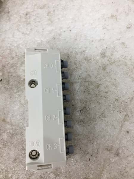
- Port Count: 4 fiber optic channels (CH0, CH1, CH2, CH3)
- Baud/Data Rate: Optical component speed: 5 MBd (plastic fiber POF, hard clad silica HCS)
- Operating Temperature: 0°C to +60°C (per drive ambient conditions)
- Isolation Rating: Meets drive-level isolation standards (500 VAC test voltage on I/O groups)
- Power Draw: +5 V DC ±10%, 200 mA maximum from control unit
- Weight: 0.11 kg (net)
- Dimensions: Compact form factor for insertion into DDCS slot on RMIO board
- Degree of Protection: IP20
- Optical Components: Agilent Technologies Versatile Link (5 MBd)
- Mounting: 20-pin header insertion with 2 M3×8 fixing screws
- EMC Standards: IEC 1000-4-2, 4-3, 4-6 (industrial immunity); EN 50081-2 (emissions)
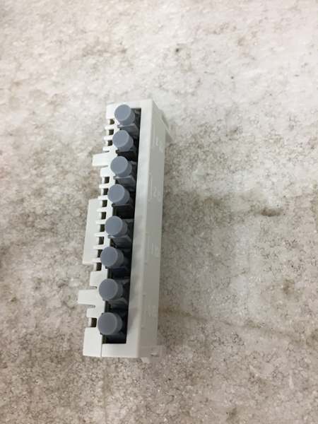
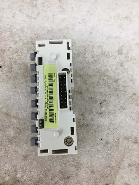
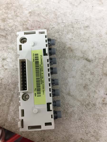
ABB RDCO-02C
The Real-World Problem It Solves
ACS800 drives need fiber optic communication to fieldbus adapters, remote I/O, and programming tools without copper cabling that’s vulnerable to electromagnetic interference. This module adds four independent optical channels, letting you connect PROFIBUS/DeviceNet adapters, master/follower links for coordinated motor control, and DriveWare PC tools through glass or plastic fiber runs up to 100 meters.
Where you’ll typically find it:
- Paper mill drive cabinets where multiple ACS800 units need master/follower fiber linking for coordinated web tension control
- Steel rolling mill drives requiring optical isolation from VFD-generated EMI to PROFIBUS DP networks
- Water treatment pump stations with remote I/O racks connected via DDCS fiber links
Bottom-line: It’s your fiber backbone for ACS800 drive communication, providing electrical isolation and long-distance connectivity where copper cables would fail due to noise or distance constraints.
Hardware Architecture & Under-the-Hood Logic
The RDCO-02C is a plug-in option board that slides into the DDCS slot on the ACS800 RMIO Motor Control and I/O board. The “C” suffix indicates conformal coating on the PCB for protection against humidity and corrosive atmospheres. The board contains four pairs of optical transmitters and receivers operating at 5 megabaud, using Agilent Technologies Versatile Link optical components.
- Channel CH0 (Overriding System) : This channel typically connects to fieldbus adapter modules (like RPBA-01 for PROFIBUS or RMBA-01 for DeviceNet), carrying drive parameters and control commands to the DCS network.
- Channel CH1 (I/O Extensions) : Handles communication with external I/O options and supply units connected through the DDCS bus, allowing remote S800 I/O or third-party I/O racks to interface with the drive.
- Channel CH2 (Master/Follower Link) : Provides optical fiber link between multiple ACS800 drives for master/follower applications, enabling load sharing and synchronized speed control across multiple motors without copper cables.
- Channel CH3 (PC Tool) : Dedicated optical port for DriveWindow/DriveWare PC tools, enabling parameter configuration, monitoring, and firmware updates via fiber optic link from a laptop in the control room.
- Optical Signal Processing: Each channel uses separate transmitter/receiver pairs with 5 MBd optical components. Light signals convert to electrical data at the RMIO board level through the 20-pin connector.
- Power and Grounding: The module draws +5V DC from the control unit via the DDCS slot connection. The two M3×8 fixing screws provide mechanical retention and establish grounding continuity between the RDCO module and RMIO board ground plane.

ABB RDCO-02C
Field Service Pitfalls: What Rookies Get Wrong
Mixing Optical Component Speeds Between Link Ends
Installing a RDCO-02C (5 MBd optical components) and connecting it to a drive or fieldbus adapter with 10 MBd optical components causes signal intensity mismatch. The transmitter overdrives the receiver, resulting in intermittent communication, CRC errors, or complete link failure that looks like a bad fiber cable.
Field Rule: Match optical component types at both ends of every fiber link. RDCO-02C uses 5 MBd components—pair it only with modules, drives, or adapters that also use 5 MBd. If your fieldbus adapter has 10 MBd optics, use an RDCO-01 or RDCO-03 instead. Mixing 5 and 10 MBd components guarantees communication problems.
Touching Fiber Ends with Bare Hands
New technicians grab fiber optic cable ends with bare fingers during installation or troubleshooting. The optical surfaces get contaminated with skin oils and dirt, causing signal attenuation and link failures that require expensive fiber replacement.
Quick Fix: Never touch the polished end faces of fiber optic cables. Handle cables by the connector body only. If contamination occurs, clean fiber ends with 99% isopropyl alcohol and lint-free optical cleaning wipes before reinserting. Dirty fiber equals dead communication, no matter how good the electronics are.
Ignoring Fiber Bend Radius Limits
Routing fiber cables through tight cable trays with sharp bends under 25 mm radius causes micro-cracks in the fiber core and total signal loss. Technicians force cables around corners to save space, creating intermittent links that fail randomly when vibration occurs.
Field Rule: Maintain minimum 35 mm short-term bend radius for all DDCS fiber cables. Use proper fiber management trays with generous bend protection. Maximum long-term tensile load is only 1 N—never pull cables tight during installation. Exceeding bend limits destroys fiber integrity, and the cable must be replaced.
Forgetting to Install Grounding Screws
New engineers insert the RDCO module and hand-tighten or forget the M3×8 fixing screws altogether. The plastic retaining clips hold the board in place, but without the screws, the module lacks proper grounding to the RMIO board and can float electrically, causing ESD susceptibility and erratic communication faults.
Field Rule: Always install both M3×8 fixing screws provided with the RDCO kit. Torque to 0.2-0.4 Nm (2-4 lbf.in). These screws aren’t just mechanical fasteners—they’re the ground path between the module and drive chassis. Missing screws means ground loops and potential communication failures during EMI events.
Installing on Powered Drive Without Discharge Time
Rookies replace RDCO modules while the drive is powered or after insufficient capacitor discharge time. The intermediate circuit capacitors in ACS800 drives hold lethal charge even with mains disconnected. Working on live boards risks electric shock and can fry the RDCO module from inrush when inserting into the DDCS slot.
Field Rule: Always switch off mains power and wait minimum 5 minutes for intermediate circuit capacitors to discharge. Verify zero voltage with a multimeter before touching any drive internals. The DDCS slot carries power and data—inserting modules into a charged drive destroys components and endangers personnel.
Commercial Availability & Pricing Note
Please note: The listed price is for reference only and is not binding. Final pricing and terms are subject to negotiation based on current market conditions and availability.


