
Description
Hard-Numbers: Technical Specifications
- Protocol Support: Modbus TCP, IEC 60870-5-104 (Ethernet), Modbus RTU/ASCII, IEC 60870-5-101 (serial), PROFIBUS DP V0/V1 (via CI modules), ABB CAN Bus
- Port Count: 4x Ethernet RJ45, 2x serial (RS-232/RS-485 configurable), 4x communication interface module slots
- Baud/Data Rate: 600-38,400 bps (serial), 100 Mbit/s Ethernet
- Operating Temperature: -20°C to +70°C
- Isolation Rating: 2500V DC (typical for industrial controllers)
- Power Draw: 24V DC (19.2-32.5V), 1A nominal current, 24W full station consumption
- Memory Size: 48MB total (16MB battery-buffered SRAM, 32MB DRAM)
- Processing Speed: 800MHz PowerQUICC II Pro CPU clock, configurable cycle times from 5ms
- Dimensions: 285mm width x 152mm height x 95mm depth
- Weight: 1.1 kg
- I/O Capacity: Up to 10 direct S700 I/O modules, 1500 I/O points total
- Redundancy: Yes, switching time 500ms
- Protection Class: IP20, CE, cULus, ISA-S71.04 G3 certified

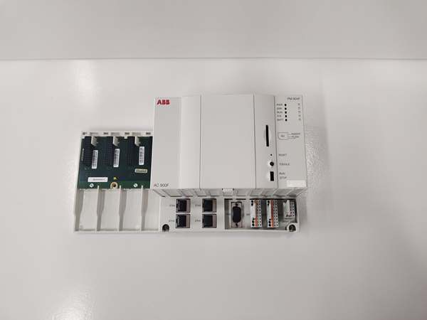
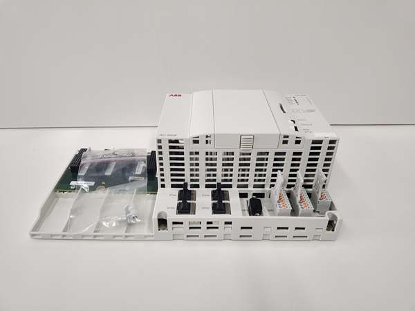
ABB PM904F 3BDH001002R0001
The Real-World Problem It Solves
DCS applications need both Ethernet connectivity for SCADA integration and fieldbus expansion for distributed I/O without choking on I/O capacity or field protocol support. This controller eliminates the need for separate communication gateways by providing 4 Ethernet ports and 4 PROFIBUS/CAN module slots in a single chassis, supporting up to 1500 I/O points with a compact footprint.
Where you’ll typically find it:
- Water treatment plant control rooms with remote PROFIBUS I/O racks
- Power plant turbine control requiring Modbus TCP to SCADA and PROFIBUS to actuators
- Chemical process skid units needing IEC 60870 telecontrol and local S700 I/O modules
Bottom-line: It’s your mid-range DCS workhorse that bridges Ethernet networks to fieldbus devices without external protocol converters.
Hardware Architecture & Under-the-Hood Logic
The PM904F uses a PowerQUICC II Pro processor (RISC architecture) running at 800MHz, with dedicated memory management separating battery-backed SRAM for critical variables and DRAM for application code. The controller features a modular architecture with two internal buses: the I/O Bus (L1-L10 slots) for direct S700 modules and the Coupler Bus (C1-C2 slots) for communication interface modules like PROFIBUS masters.
- Program Execution: The CPU fetches and executes control logic from 32MB DRAM application memory, with multitasking support for cyclic tasks (configurable from 5ms), event-driven tasks, and PLC-mode execution running as fast as possible.
- Ethernet Communication Processing: Four onboard Ethernet ports handle TCP/IP traffic via dedicated MAC/PHY controllers. Port 1-2 typically serve ControlNet and redundancy links, while ports 3-4 handle Modbus TCP and IEC 60870-5-104 telecontrol protocols independently.
- Serial Interface Handling: Two serial ports (SER1, SER2) use pluggable terminal blocks with spring connections, configurable via software for RS-232 or RS-485 operation. SER1 handles Modbus RTU/ASCII or IEC 60870-5-101 telecontrol; SER2 is a dedicated RS-232 diagnostic port for radio clock and engineering tool connection.
- Fieldbus Module Integration: The Coupler Bus supports up to 4 communication interface modules. CI773F PROFIBUS DP master modules provide DP-V0/V1 protocol support at 9.6-12 Mbit/s, while CI910F CAN Bus modules connect to Freelance Rack I/O at 100 or 500 kbit/s.
- I/O Data Exchange: The I/O Bus connects up to 10 S700 I/O modules directly via terminal units, with scan times as fast as 2ms possible. Each I/O module features short-circuit and line-break detection per channel, with data exchanged through the CPU’s internal bus architecture.
- Redundancy Switchover: In redundant configuration, both primary and backup CPUs execute identical applications continuously. When the primary fails, the backup assumes control within 500ms, maintaining process continuity through synchronized state data exchanged via dedicated redundancy links.
ABB PM904F 3BDH001002R0001
Field Service Pitfalls: What Rookies Get Wrong
Misconfiguring Serial Port Electrical Standards
New techs set the serial port for RS-485 mode in software but wire the pluggable terminal block for RS-232 (or vice versa). This causes communication failures with Modbus RTU devices or telecontrol equipment, leading to “communication timeout” alarms that look like device problems but are actually physical layer mismatches.
Field Rule: Always verify the software configuration matches the physical terminal block wiring before powering up. SER1 supports RS-232 or RS-485 via configurable DIP settings and software parameters—check both. Use the correct spring-cage terminal block (TU 715F screw-type or TU 716F spring-type) and confirm baud rate settings (600-38,400 bps) match the field device exactly.
Ignoring Battery Backup Warning During Cold Retain Setup
Engineers configure critical variables for cold retain (permanent storage across power loss) but ignore the battery low warning LED. When the lithium battery (TA 951F) fails after 2+ years, all cold-retain values including lifetime counters and metering data disappear during the next power cycle—data that can’t be recovered without manual re-entry.
Quick Fix: Check the BATTERY LED status during routine maintenance. Replace the lithium backup battery when the warning appears—ABB gives about 14 days of warning before charge becomes critical. Always verify cold-retain variable retention after battery replacement by cycling power and checking that persistent values survived the outage.
Overloading the 24V Power Supply with Full Station Assembly
Rookies calculate only the CPU module’s power draw (1A nominal, 24W max) without accounting for all attached S700 I/O modules, communication interface cards, and optional display unit. This causes voltage dips during startup inrush (1.5A) or intermittent brownouts that trigger unpredictable CPU restarts and I/O communication failures.
Field Rule: Calculate total station power consumption including all I/O modules, CI/CM communication cards, and display units. Ensure your 24V DC power supply can handle full load with margin—the PM904F alone draws up to 1A, and each S700 I/O module adds current. Use sufficiently sized conductors (verify cross-section per ABB installation manual) and separate power cables from signal/data cables by at least 20cm to prevent EMI issues.
Mixing Up Redundant CPUs with Different Firmware Versions
After replacing a failed PM904F CPU in a redundant pair, technicians download the application without verifying both CPUs run identical firmware versions. Version mismatches cause synchronization failures between primary and backup, leading to “redundancy lost” faults and the backup CPU unable to take over during switchover events.
Field Rule: Always match firmware versions across both redundant controllers before commissioning. Use Freelance Engineering to verify CPU firmware, then apply updates to both CPUs if needed. The backup CPU must execute the exact same code version as the primary for the 500ms switchover to function correctly—any deviation risks process interruption during failure events.
Commercial Availability & Pricing Note
Please note: The listed price is for reference only and is not binding. Final pricing and terms are subject to negotiation based on current market conditions and availability.


