
Description
Key Technical Specifications
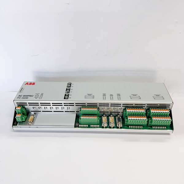
- Model Number: PCD235C101 3BHE057901R0101
- Manufacturer: ABB
- System Compatibility: ABB Unitrol PCD235 Excitation Control System
- Analog Inputs: 3 channels (±10V or ±20mA) for field voltage/current monitoring
- Analog Outputs: 3 channels (±10V) for exciter control signals
- Temperature Inputs: 3 channels for PT100/PTC temperature sensors (exciter winding, bearing temperature monitoring)
- Digital I/O: 8 digital inputs, 6 digital outputs (including relay outputs for alarm/control)
- Communication Interfaces: Profibus DP (master/slave), RS485, 3 fiber-optic links for high-speed data transfer
- Isolation Rating: 2500V AC (field-to-logic, channel-to-channel)
- Operating Temperature Range: -40°C to +70°C (industrial grade)
- Power Supply: 24V DC (redundant input option)
- Power Consumption: <5W typical
- Dimensions: 160mm x 100mm x 30mm (standard Unitrol module size)
- Mounting: Rack-mounted (3U height, compatible with Unitrol PCD235 cabinets)
- Status Indicators: Power LED, Communication LED, System Fault LED, Channel Status LEDs
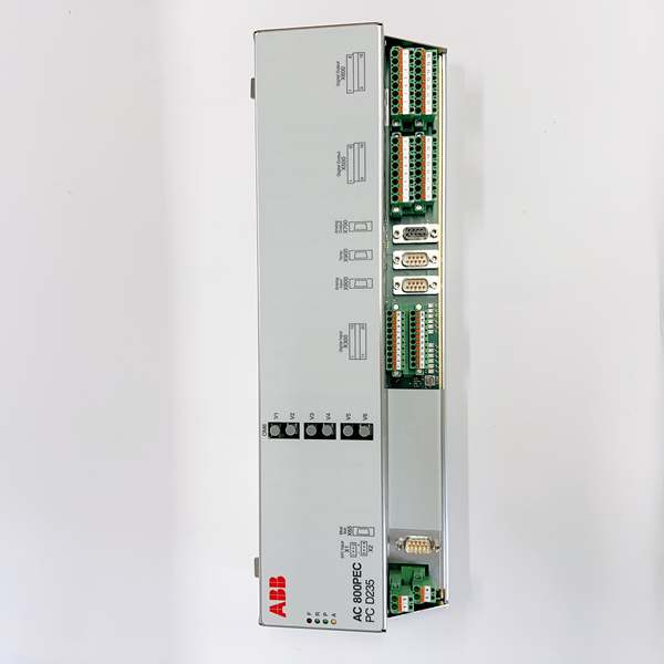
ABB PCD235C1013BHE057901R0101
Field Application & Problem Solved
In power generation environments—coal, gas, hydro, and nuclear power plants—the biggest challenge for synchronous generators is voltage stability and grid synchronization. Fluctuations in grid load, generator speed, or field current can cause voltage sags, swells, or even complete generator disconnection from the grid, leading to costly power outages. Legacy excitation systems often lacked the precision, communication capabilities, and diagnostic features needed for modern grid requirements.
The PCD235C101 solves this by providing high-precision serial excitation control for Unitrol systems. You’ll typically find this module in power plants controlling steam, gas, or hydro turbines—especially in plants requiring grid code compliance (like IEEE 1547 or IEC 61850). Its core value lies in maintaining generator terminal voltage within 0.5% of setpoint during normal operation and providing fast transient response (≤100ms) during grid disturbances. This prevents voltage collapse and ensures the generator stays synchronized with the grid during fault conditions.
For maintenance teams, the PCD235C101’s advanced diagnostics reduce troubleshooting time by 60% compared to older analog excitation systems. The fiber-optic communication links provide noise-free data transfer between the control module and power electronics, eliminating electromagnetic interference (EMI) issues common in copper-based systems. Additionally, the Profibus DP interface enables seamless integration with plant DCS systems for remote monitoring and control—critical for modern power plant operations.
Installation & Maintenance Pitfalls (Expert Tips)
Fiber-Optic Link Polarity is Non-Negotiable
A common rookie mistake is reversing the TX/RX polarity on fiber-optic cables. The PCD235C101 uses 3 fiber-optic links for high-speed communication with the exciter power stage (GSD231/GSD232 modules). Reverse polarity will cause “communication timeout” faults and complete loss of excitation control. My rule: Always use color-coded cables (TX = red, RX = blue) and verify polarity with a fiber-optic tester before closing the cabinet.
Redundant Power Supply Wiring Saves Lives
The PCD235C101 supports redundant 24V DC power inputs, but many installers wire both inputs to the same power source. This defeats the purpose of redundancy. In the field, a single power supply failure has caused complete generator shutdowns costing $100k+/hour in lost production. The fix: Connect each power input to a separate 24V DC power supply with independent circuit breakers. Verify redundancy by simulating a power failure on one supply during commissioning.
Analog Calibration Drift Causes Voltage Instability
Over time (typically 2-3 years), the PCD235C101’s analog input/output channels drift out of calibration. This leads to “voltage regulation error” alarms and unstable generator operation. Rookies often replace the entire module, but calibration is a simple procedure using ABB’s WinPCD software. My recommendation: Calibrate all analog channels annually during scheduled outages. Use a precision calibrator (±0.01% accuracy) and document results for trend analysis.
Grounding Loops Ruin Communication
The PCD235C101 has isolated communication interfaces, but improper grounding can still create loops that introduce noise into Profibus DP and RS485 networks. This causes intermittent communication drops and data corruption. The solution: Use single-point grounding for all communication cables (ground only at the DCS end) and install surge protectors on all field wiring. For Profibus DP, use shielded twisted-pair cable with a minimum 90% coverage and terminate with 120-ohm resistors at both ends of the bus.

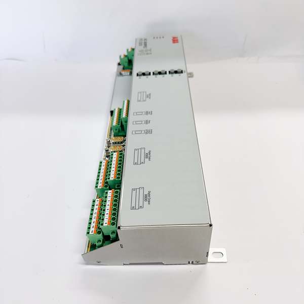
ABB PCD235C1013BHE057901R0101
Technical Deep Dive & Overview
The PCD235C101 is a microprocessor-based serial excitation control module designed for ABB’s Unitrol PCD235 system—the workhorse of power plant excitation control. It connects to the Unitrol backplane via a 96-pin edge connector, communicating with the main controller (PCD235A101) and power stage modules (GSD231/GSD232) through fiber-optic links and the Profibus DP network.
Internally, the module uses a 32-bit microprocessor running ABB’s proprietary excitation control algorithms—including automatic voltage regulation (AVR), reactive power control (Q-control), and power system stabilizer (PSS) functions. The 3 analog inputs monitor generator terminal voltage, field current, and grid frequency, while the 3 analog outputs provide control signals to the exciter power stage (thyristor firing pulses). The temperature inputs monitor critical components like exciter windings and bearings, triggering alarms or shutdowns if temperatures exceed safe limits.
The PCD235C101’s fiber-optic links are a game-changer in harsh industrial environments—they eliminate EMI/RFI interference from nearby high-voltage equipment and provide data transfer rates up to 10 Mbps with <1ms latency. The Profibus DP interface enables integration with plant DCS systems for remote monitoring, control, and data logging. Status LEDs provide real-time feedback: a green power LED confirms both power supplies are active, a yellow communication LED indicates active fiber-optic/Profibus communication, and red fault LEDs highlight specific issues (analog calibration error, communication failure, temperature alarm).
In the field, the PCD235C101 is the “brain” of the excitation system—ensuring generators operate safely, efficiently, and in compliance with grid codes. Its modular design allows for easy replacement during scheduled outages, while its advanced diagnostics reduce unplanned downtime by providing early warning of potential issues. For power plant operators, this module is critical for maintaining grid stability, maximizing generator efficiency, and avoiding costly outages.


