
Description
Hard-Numbers: Technical Specifications
- Input Power Voltage: 100-240 VAC / 48-250 VDC (wide-range)
- Control Power Consumption: ≤2.5W nominal
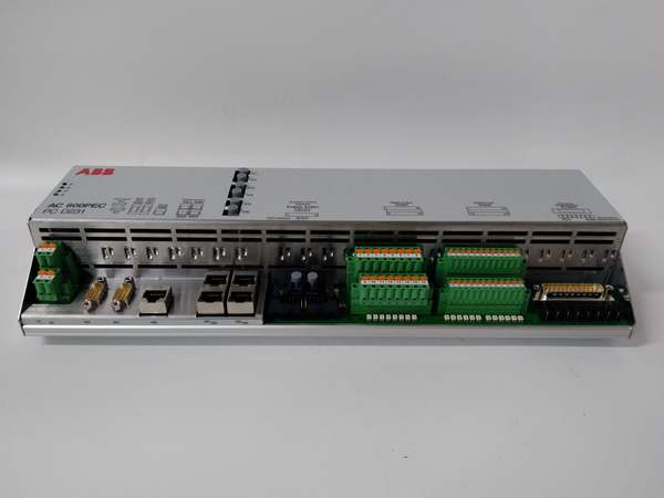
- Binary Outputs: 6BO (6 Binary Outputs)
- Communication Protocols: DNP3, IEC 60870-5-101/104, Modbus RTU/TCP, Modbus TCP
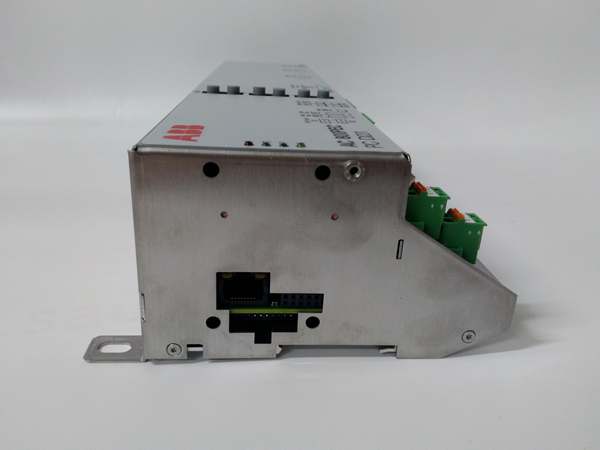
- Ethernet Interface: Built-in 10/100Mbps Ethernet port
- Serial Interface: RS-485 (COM ports)
- Operating Temperature: -25°C to +60°C
- Storage Temperature: -40°C to +85°C
- Humidity Tolerance: 5% to 95% (non-condensing)
- Isolation Voltage: 1500V AC (input to output)
- Weight: 1.43 kg
- Dimensions: 142 mm × 73.5 mm × 373 mm (L × W × H)
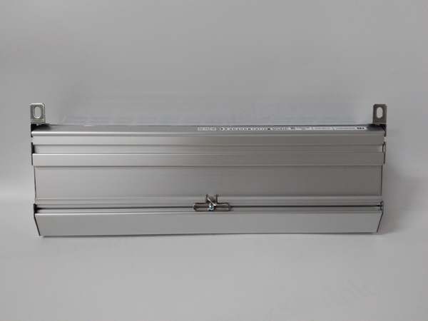
- Mounting Type: Standard 19-inch rack or cabinet mounting

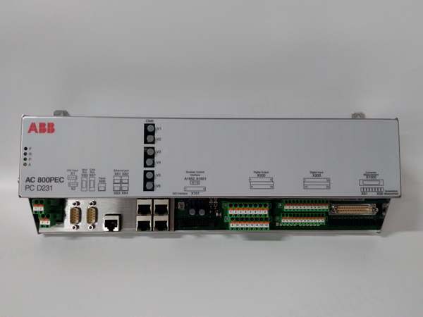
ABB PCD231B101 3BHE025541R0101
The Real-World Problem It Solves
You’ve got a high-speed AC 800PEC controller running complex algorithms, but it needs to talk to a power converter or excitation system that doesn’t speak its language. The PCD231B101 acts as the translation layer—taking high-speed control commands from the AC 800PEC and converting them into the precise gate signals your converter needs to fire thyristors or IGBTs at the right moment.
Where you’ll typically find it:
- Power plant excitation systems using ABB UNITROL 6000 static exciters
- Industrial drive applications with DCS800 series DC converters
- Aluminum potline control systems requiring precise rectifier bridge control
- Traction propulsion systems in marine and rail applications
This module keeps your power electronics synchronized with your control logic—without it, your fancy controller is just a brick.
Hardware Architecture & Under-the-Hood Logic
The PCD231B101 sits between the AC 800PEC controller backplane and the power converter/excitation system, functioning as a dedicated interface card with its own processing logic. It’s not a passive adapter—it actively translates control commands, handles fault diagnostics, and manages communication with both the controller and the power converter.
Internal Signal Flow:
- Control commands arrive from AC 800PEC via backplane bus (high-speed optical or electrical)
- Interface microprocessor validates commands and maps them to appropriate output channels
- Binary outputs generate gate firing signals for converter thyristors/IGBTs
- Feedback signals from converter (current, voltage, status) are conditioned and digitized
- Processed feedback is transmitted back to AC 800PEC controller for closed-loop control
- Communication ports (Ethernet, RS-485) handle parameter exchange and diagnostic data
- Watchdog circuit monitors converter interface health; faults trigger alarm states
- Protection logic can override controller commands if hardware limits are exceeded
ABB PCD231B101 3BHE025541R0101
Field Service Pitfalls: What Rookies Get Wrong
Mix Up Wide-Range Power Inputs
I’ve seen techs apply 24V DC control power because “that’s what the PLC uses” and wonder why the module won’t boot. The PCD231B101 requires a wide input range—100-240V AC or 48-250V DC. Feed it 24V and nothing happens, not even a fault light, because it never powers up the internal circuitry.
Field Rule: Verify cabinet supply voltage before connecting. If you only have 24V available, you need an external step-up converter or DC-DC supply—this module won’t run on control voltage alone.
Ignore the Ground Reference Between Controller and Converter
Young engineers float the ground reference “to avoid ground loops” and then complain about erratic converter behavior or random trips. The PCD231B101 needs a solid ground reference between the AC 800PEC controller and the power converter backplane—otherwise, your firing signals drift relative to the converter’s internal timing, and you get missed gate pulses or spurious triggering.
Quick Fix: Bond the chassis grounds of the AC 800PEC rack, the PCD231B101 chassis, and the power converter cabinet with a minimum 6mm² copper conductor. Use star grounding at a single point—no daisy chains. Verify ground continuity with a multimeter before applying power.
Forget to Configure the Binary Output Timing
Techs assume the binary outputs fire immediately when the controller sends a command, but the PCD231B101 has configurable timing parameters (delay, pulse width, deadband). If you leave these at default settings from a different application, your converter might fire too late for your load characteristics, or the pulse width might be too narrow to properly trigger the thyristor gates.
Quick Fix: Check the timing configuration in the AC 800PEC Control Builder PEC project. Verify that the firing delay and pulse width match your converter manufacturer’s specs—typically 50-200µs pulse width with adjustable phase delay for SCR-controlled bridges.
Skip the Converter Feedback Wiring During Replacement
When swapping a failed PCD231B101, rookies connect only the output gate signals and forget the feedback inputs from the converter. The module will send firing commands, but without voltage/current feedback, your closed-loop control is flying blind. The AC 800PEC controller sees zero feedback and ramps up command output—then your converter trips on overcurrent or you cook your field winding.
Quick Fix: Label every wire before removal. Connect all feedback channels (current shunts, voltage dividers, status contacts) before powering up. Verify feedback scaling matches the AC 800PEC project configuration—if you’re off by a decimal point, your control loop oscillates.
Commercial Availability & Pricing Note
Please note: The listed price is for reference only and is not binding. Final pricing and terms are subject to negotiation based on current market conditions and availability.


