
Description
Key Technical Specifications
-
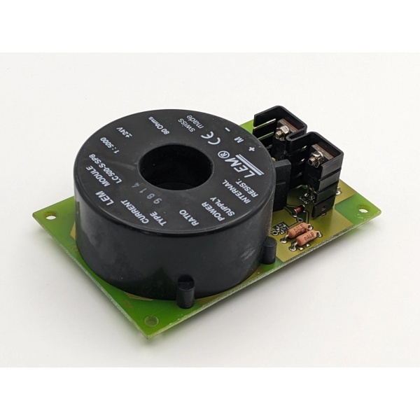
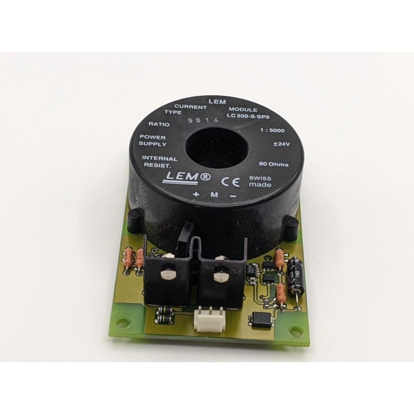
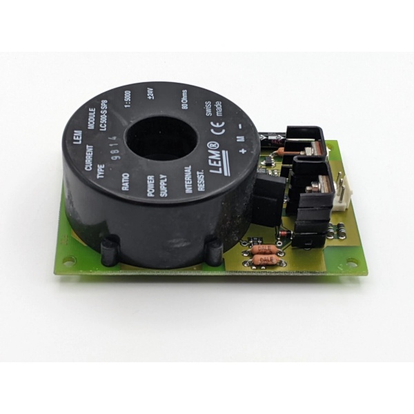
Model Number: LC500-S/SP8
-
Manufacturer: ABB Automation GmbH (Force Measurement)
-
Rated Current: 1000 A (bidirectional)
-
Ratio: 1:2000 (output current to primary current)
-
Supply Voltage: ±24 V DC (±5 %)
-
Output Signal: Differential current (mA) proportional to primary
-
Accuracy Class: 0.5 % (typical)
-
Bandwidth: DC … 100 kHz (−3 dB)
-
Isolation: 4 kV AC (primary to secondary)
-
Operating Temperature: −25 °C … +70 °C
-
Mounting: DIN-rail or panel, 4 × M6 through-holes
-
Dimensions: 125 × 65 × 45 mm (approx.)
-
Weight: 0.7 kg
-
RoHS: Compliant

ABB LC500-S/SP8
Field Application & Problem Solved
On older AC- or DC-drive skids the biggest headache is getting a true RMS current into the PLC without adding another CT or shunt. LC500-S/SP8 drops straight onto the bus-bar—no core split, no bus-work modification—and gives you a millivolt-level differential current that’s already scaled 1:2000. You’ll typically find it strapped around the main motor feed in paper mills, on the DC-link of extruder drives, or inside grid-tie inverters where you need <0.5 % accuracy for revenue metering. Core value: it’s Hall-effect, so DC offset and high-frequency switching noise don’t saturate the core—your PLC sees a clean 0-20 mA loop proportional to 0-1000 A bidirectional.
On older AC- or DC-drive skids the biggest headache is getting a true RMS current into the PLC without adding another CT or shunt. LC500-S/SP8 drops straight onto the bus-bar—no core split, no bus-work modification—and gives you a millivolt-level differential current that’s already scaled 1:2000. You’ll typically find it strapped around the main motor feed in paper mills, on the DC-link of extruder drives, or inside grid-tie inverters where you need <0.5 % accuracy for revenue metering. Core value: it’s Hall-effect, so DC offset and high-frequency switching noise don’t saturate the core—your PLC sees a clean 0-20 mA loop proportional to 0-1000 A bidirectional.
Installation & Maintenance Pitfalls (Expert Tips)
±24 V ripple matters – Keep ripple <200 mV p-p. High ripple introduces offset drift and you’ll chase phantom overloads.
Mounting torque – 4 N·m on the bus-bar bolts. Undertorque and you get hot-spots; over-torque and you crack the ceramic Hall insert.
Output wiring trap – Use twisted-pair shielded cable and land shield at ONE end only. Land both ends and you’ll inject VFD switching noise into the 4-20 mA loop.
Primary current direction – Arrow on the case must match line flow. Reverse it and your PLC sees negative mA—easy fix, but it confuses operators during start-up.
Zero/span trim – Factory sets zero at 0 A, but if you run unbalanced DC links, use the trim pot to null the offset before you commission.
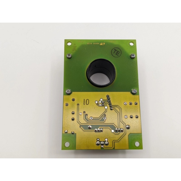
ABB LC500-S/SP8
Technical Deep Dive & Overview
LC500-S/SP8 is a closed-loop Hall-effect transducer. Inside: Hall sensor, compensation coil, and a small op-amp loop that forces the coil current to null the magnetic field. Result: output current is exactly proportional to primary current and independent of temperature or core non-linearity. No user firmware—just land ±24 V, read the diff current across a 100 Ω precision resistor, and you have 0-20 mA for 0-1000 A. Lose ±24 V and the output goes open—tie it to the same UPS feeding your analog card.
LC500-S/SP8 is a closed-loop Hall-effect transducer. Inside: Hall sensor, compensation coil, and a small op-amp loop that forces the coil current to null the magnetic field. Result: output current is exactly proportional to primary current and independent of temperature or core non-linearity. No user firmware—just land ±24 V, read the diff current across a 100 Ω precision resistor, and you have 0-20 mA for 0-1000 A. Lose ±24 V and the output goes open—tie it to the same UPS feeding your analog card.


