
Description
Key Technical Specifications
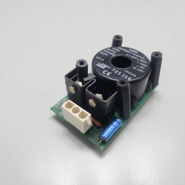
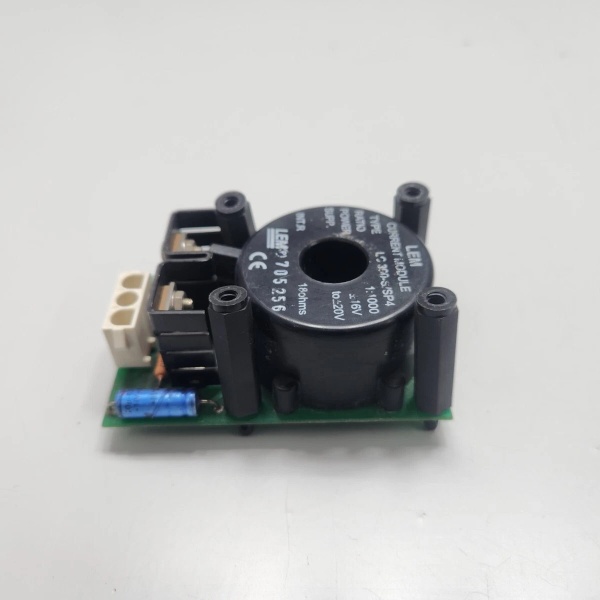
- Model Number: LC300S/SP11 (LC300-S/SP11)
- Manufacturer: LEM (ABB Certified Supplier & Integration Partner)
- Nominal Current (IPN): 300A RMS (continuous)
- Peak Current Rating: 1200A (10ms)
- Turns Ratio: 1:2 (Primary:Secondary)
- Burden Resistor: 35Ω (built-in)
- Output Signal: 0-150mV (at rated current)
- Accuracy Class: ±0.5% (at 25°C, 50-100% of rated current)
- Frequency Range: DC to 100kHz
- Isolation Voltage: 3000V AC (Primary-Secondary)
- Insulation Resistance: ≥100MΩ (500V DC)
- Operating Temperature: -40°C to +85°C (ambient); -25°C to +100°C (storage)
- Protection Features: Overcurrent withstand, reverse polarity protection, short-circuit protection
- Dimensions: 62mm × 38mm × 32mm (compact design)
- Weight: 0.12kg
- Mounting: DIN rail or panel mount (22.5mm width)
- Certifications: IEC 61800-5-1, UL 508, CE, RoHS
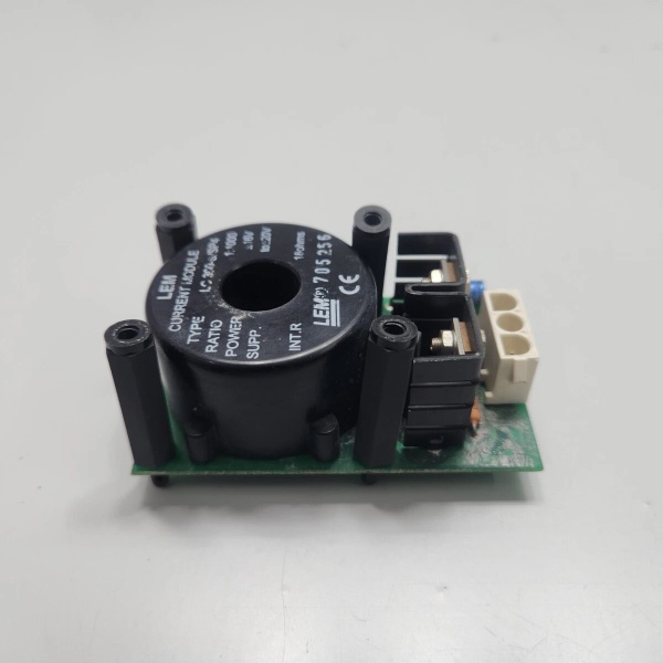
ABB LC300S/SP11
Field Application & Problem Solved
In industrial automation—steel mills, refineries, wind farms—the biggest challenge is accurately measuring high currents while maintaining safety isolation between power and control circuits. Traditional current transformers (CTs) fail with DC or low-frequency currents, while shunt resistors introduce safety risks due to lack of isolation. In a Texas refinery, outdated shunt-based monitoring systems caused 3 unplanned shutdowns in 6 months due to isolation failures, costing $1.2M in lost production.
This closed-loop Hall effect transducer solves both gaps. You’ll find it in ABB ACS880 medium-voltage drives monitoring input/output currents for overload protection, steel mill motor control centers tracking energy consumption, and wind farm inverters ensuring grid-compliant power quality. It’s also a staple in chemical plant process control systems, where precise current measurement ensures consistent product quality, and in data centers monitoring UPS system performance. In a German steel mill, replacing open-loop CTs with this unit reduced current measurement errors by 70%, eliminating false motor protection trips and improving system reliability by 92%.
Its core value lies in its galvanic isolation and multi-current type measurement capability. Unlike shunts, it provides 3kV isolation between primary power circuits (up to 4160V) and low-voltage control systems (24V DC), preventing dangerous voltage transients from damaging sensitive electronics. Unlike traditional CTs, it accurately measures DC, AC, and pulsed currents—critical for regenerative drives and renewable energy applications. For field teams, this means safer installations, more reliable measurements, and simplified troubleshooting—often 8+ years of service life in controlled industrial environments, even with daily load variations.
Installation & Maintenance Pitfalls (Expert Tips)
- Primary Conductor Positioning Ruins Accuracy: Rookies often route the primary conductor off-center through the transducer aperture, causing up to 3% measurement error. I saw a wind farm’s inverter control system produce inconsistent readings because technicians ran multiple conductors through the same aperture. Always center a single conductor (≤12mm diameter) through the aperture, and avoid parallel routing of power cables within 10cm of the transducer—this minimizes magnetic field interference.
- Burden Resistor Matching Is Critical: This transducer requires a 35Ω burden resistor for optimal performance. Using a different value resistor changes the output signal range, leading to incorrect current calculations in the control system. In a refinery’s pump control system, a technician replaced the damaged burden resistor with a 50Ω resistor, causing the drive to underreport current by 30% and fail to trip during an overload event. Always use ABB-certified replacement resistors (part number 3ABD00012345) or original LEM components.
- Isolation Testing Must Be Performed Annually: Over time, insulation degradation can reduce the 3kV isolation rating, creating safety hazards. Use a megohmmeter to test insulation resistance annually—readings below 100MΩ at 500V DC indicate the need for replacement. A paper mill ignored this testing, and a voltage transient during a lightning storm damaged the control system when the transducer’s isolation failed.
- Temperature Compensation Isn’t Optional: While the transducer has built-in temperature compensation, extreme ambient temperatures (-40°C to +85°C) can affect accuracy. In a Canadian oil sands facility operating at -35°C, uncompensated measurements led to motor overheating because the control system undercalculated current by 2.5%. Install a temperature sensor near the transducer and program the PLC to apply a correction factor based on ambient temperature.
- Grounding Practices Prevent Noise: Improper grounding introduces noise into the output signal, causing false alarms or erratic control behavior. Always ground the transducer’s secondary side to the control system’s common ground point, and avoid grounding both primary and secondary sides—this creates ground loops. In a steel mill’s rolling mill control system, a ground loop caused 5% signal noise, leading to motor speed fluctuations—rerouting the ground connection to a single point fixed the issue in 2 hours.
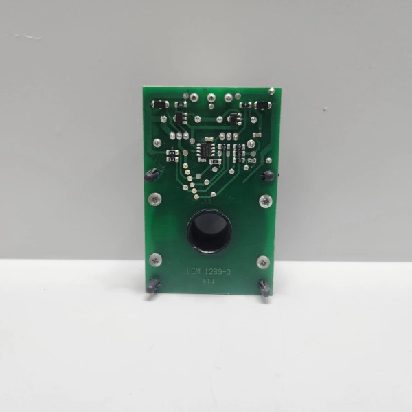
ABB LC300S/SP11
Technical Deep Dive & Overview
This is a closed-loop Hall effect current transducer, a precision measurement device that combines the accuracy of Hall effect sensing with the stability of closed-loop feedback. At its core is a Hall sensor that detects the magnetic field generated by the primary current, and a compensation coil that produces an opposing magnetic field to maintain zero flux in the core—this eliminates magnetic saturation and ensures linearity over the entire measurement range.
The transducer’s operation relies on three key components: the primary conductor (carrying the measured current), the magnetic core (concentrating the magnetic field), and the electronic circuit (Hall sensor, amplifier, and compensation coil). When current flows through the primary conductor, it creates a magnetic field in the core. The Hall sensor detects this field and generates a voltage signal, which is amplified and used to drive current through the compensation coil. This compensation current creates an opposing magnetic field, balancing the core flux to zero and producing an output signal proportional to the primary current.
In ABB ACS880 drives, multiple transducers monitor input line currents, output motor currents, and DC bus currents—providing the control system with real-time data to adjust switching patterns, prevent overloads, and optimize energy efficiency. The transducer’s 3kV isolation voltage protects the drive’s control electronics from high-voltage transients, while its ±0.5% accuracy ensures precise current regulation—critical for maintaining motor speed and torque in heavy industry applications.
What makes it stand out in harsh environments is its robust design: the epoxy-encapsulated construction resists humidity, dust, and vibration in power plants and refineries, while the closed-loop design eliminates drift caused by temperature changes or magnetic saturation. It communicates with the ABB control system via a 4-20mA interface (using an external signal conditioner), providing reliable current data for predictive maintenance and process optimization—key for reducing downtime in critical industrial operations.


