Description
Component Snapshot At-a-Glance
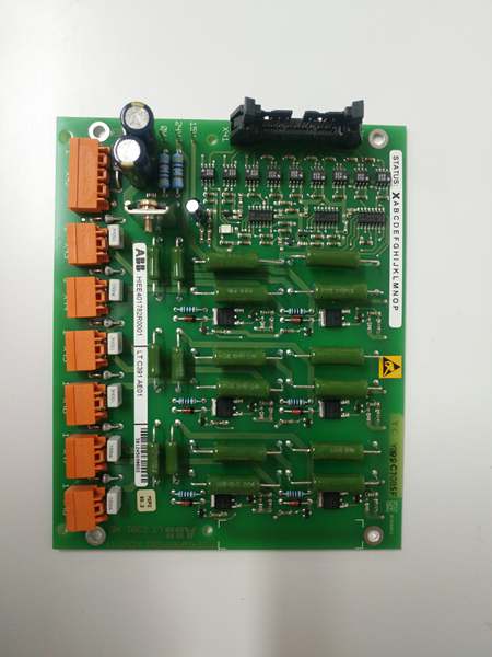
- Model: HIEE401782R0001 (LTC391AE01)
- Alt. P/N: LTC391AE01
- Product Series: ABB ACS6000 Medium-Voltage Drives, AC 800M/800xA DCS
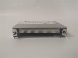
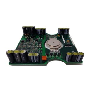
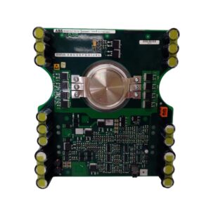
- Hardware Type: IGBT gate control & interface board (low-voltage door module)
- Key Feature: 2500V isolation, 2µs gate drive delay, integrated fault monitoring for IGBT stacks
- Primary Field Use: Controls and monitors IGBT power stages in 6kV–10kV medium-voltage drives for fans, pumps, and conveyors.
HIEE401782R0001
Hard-Numbers: Technical Specifications
- Power Input: 24VDC ±15% (18–30VDC), 15W max, reverse-polarity protected
- Gate Drive Channels: 6 independent IGBT gate outputs (per stack)
- Protocol Support: PROFIBUS DP, Modbus RTU, ABB S800 I/O Bus
- Communication Ports: 1×RS-485, 1×PROFIBUS DP, 1×S800 backplane
- Isolation Rating: 2500VAC (gate-to-logic, 1-minute withstand)
- Operating Temperature: -20°C to +60°C (rated), -40°C to +85°C (storage)
- Response Time: ≤2µs (gate signal propagation)
- Switching Frequency: Up to 2kHz (IGBT PWM control)
- Dimensions: 195mm × 115mm × 40mm (rack-mount)
- Weight: ~0.36kg
- Certifications: CE, RoHS
The Real-World Problem It Solves
Medium-voltage drive IGBT stacks need precise, isolated gate signals. Generic drivers fail under high dv/dt noise, causing shoot-through faults and catastrophic IGBT failure.
Where you’ll typically find it:
- Power plant boiler feed pumps and forced draft fan MV drives
- Mining/metals high-power conveyors and rolling mill drives
- Oil/gas refinery large motor variable-frequency drives (VFDs)
This board delivers isolated, high-speed gate control and real-time fault detection to prevent IGBT destruction and unplanned drive trips.
Hardware Architecture & Under-the-Hood Logic
This is a mixed-signal board with gate drive power supplies, opto-isolators, and fault logic—no user-programmable CPU.
- 24VDC input feeds isolated DC/DC converters; generates ±15V for IGBT gate bias.
- PWM commands from controller pass through opto-couplers (2500V isolation) to gate drive circuits.
- Gate drivers source/sink ±5A peak current to charge/discharge IGBT gates in <2µs.
- Desaturation and overcurrent sensors monitor each IGBT; fault signals latch and send to controller.
- Backplane interface reports status (OK/FAULT) and receives drive enable/disable commands.
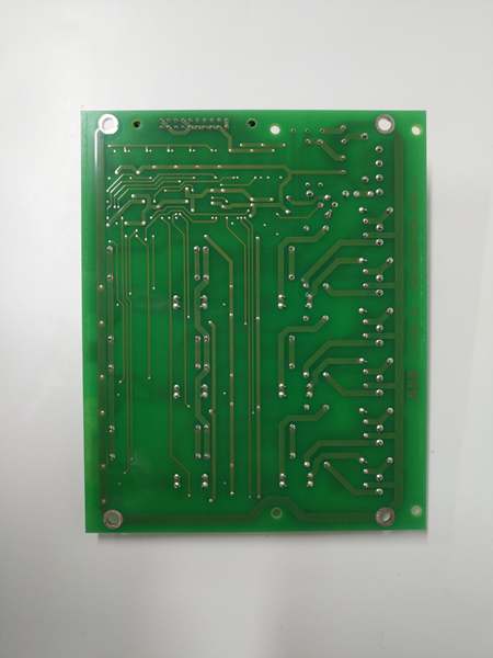
HIEE401782R0001
Field Service Pitfalls: What Rookies Get Wrong
Undersizing 24VDC Power Supply
Rookies use 10W supplies. Under peak gate current, voltage droops, causing IGBT misfire and overcurrent trips.
- Field Rule: Use ≥30W 24VDC supply; derate 50% in cabinets >45°C.
Ignoring Gate Wire Twisting & Shielding
Rookies run untwisted, unshielded gate wires parallel to power cables. Inductive coupling causes false gate triggering.
- Quick Fix: Twist gate pairs (1 twist/5cm); use shielded cable, ground shield one end only at this board.
Mismatched Gate Resistor Values
Rookies swap gate resistors between channels. Uneven switching speeds cause current imbalance and IGBT overheating.
- Field Rule: Match all 6 channel resistors to ±1% tolerance; never mix 10Ω/15Ω values.
Commercial Availability & Pricing Note
Please note: The listed price is for reference only and is not binding. Final pricing and terms are subject to negotiation based on current market conditions and availability.