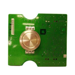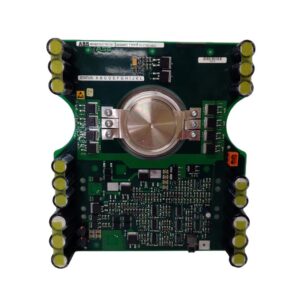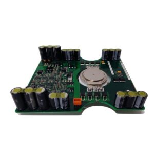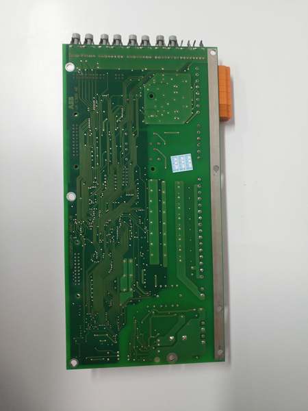
Description
Component Snapshot At-a-Glance
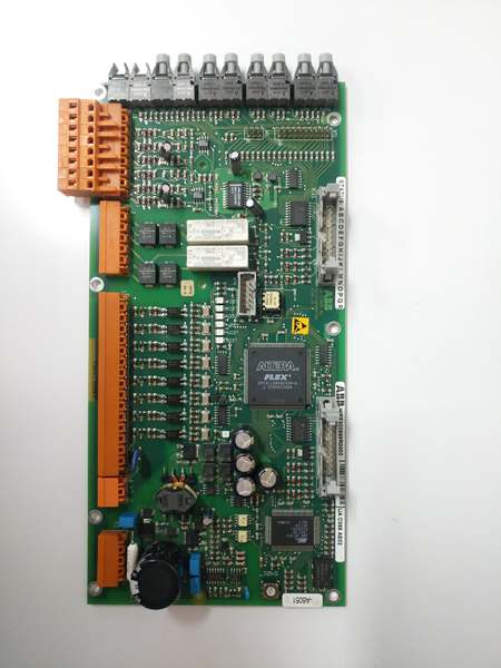
- Model: HIEE300888R0002 (UAC389AE02)
- Alt. P/N: No direct cross-reference part number
- Product Series: ABB UAC Series, 800xA DCS, ACS6000 MV Drives, UNITROL Excitation Systems
- Hardware Type: Integrated mixed I/O and real-time control board
- Key Feature: Onboard 32-bit RISC processor plus 2500 VAC isolation for all I/O channels
- Primary Field Use: Executes control logic and processes analog/digital signals for generator excitation and medium voltage drive systems.
HIEE300888R0002
Hard-Numbers: Technical Specifications
- Protocol Support: PROFIBUS DP, Modbus RTU, RS-485, ABB proprietary backplane bus
- Port Count: 16 analog input channels, 12 discrete I/O channels
- Baud Rate: PROFIBUS up to 12 Mbps, Modbus RTU up to 115.2 kbps
- Isolation Rating: 2500 VAC I/O to backplane and chassis
- Operating Temperature: -20 °C to +60 °C continuous operation
- Power Draw: 6 W typical, powered by 24 VDC ±20% supply
- Analog Signal Range: 4–20 mA, 0–10 V configurable
- ADC Resolution: 16-bit for analog sampling
- Accuracy: ±0.2% full scale at nominal temperature
- Storage Temperature: -40 °C to +85 °C
The Real-World Problem It Solves
Separate controller and I/O cards add rack space and create extra connection points for faults. Low isolation ratings let electrical noise distort readings and disrupt closed-loop control.
Where you’ll typically find it:
- Generator UNITROL excitation panels for voltage and current regulation loops
- ACS6000 medium voltage drive cabinets for motor control and protection logic
- 800xA DCS racks for auxiliary plant process control and interlock handling
This combined controller and I/O design cuts wiring points, maintains signal purity and stabilizes critical control loops.
Hardware Architecture & Under-the-Hood Logic
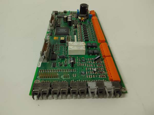
This board carries a dedicated 32-bit RISC processor for local logic and loop control. All I/O circuits use opto-isolation to separate field wiring from internal logic.
- Field analog and discrete signals enter front screw terminals and pass through input filtering circuits.
- Opto-isolators block common-mode noise and maintain 2500 VAC isolation across all channels.
- Analog signals convert to digital values via 16-bit ADC before reaching the main processor.
- Onboard processor runs control algorithms, interlock logic and fault detection routines.
- Processed data transmits over fieldbus or backplane to higher-level controllers; front LEDs show channel and module status.
HIEE300888R0002
Field Service Pitfalls: What Rookies Get Wrong
Running Signal Cables Parallel to Power Wiring
Technicians route I/O cables alongside 480 VAC or medium voltage power lines. Induced noise causes drifting analog values and erratic discrete states.
- Field Rule: Maintain a minimum 30 cm gap between signal cables and power cables. Use separate cable trays at all times.
Improper Shield Termination on Analog Lines
Grounding cable shields at both the field end and cabinet end creates ground loops. Readings fluctuate during motor startups and load changes.
- Quick Fix: Ground shield only at the module cabinet. Trim and insulate shield strands at the field device side.
Applying Incorrect Supply Voltage
Connecting 120 VAC or higher voltage directly to the 24 VDC power terminals burns internal regulators and renders the board inoperable.
- Field Rule: Verify supply is 24 VDC before powering up. Install dedicated circuit protection for this module’s power feed.
Commercial Availability & Pricing Note
Please note: The listed price is for reference only and is not binding. Final pricing and terms are subject to negotiation based on current market conditions and availability.