
Description
Key Technical Specifications
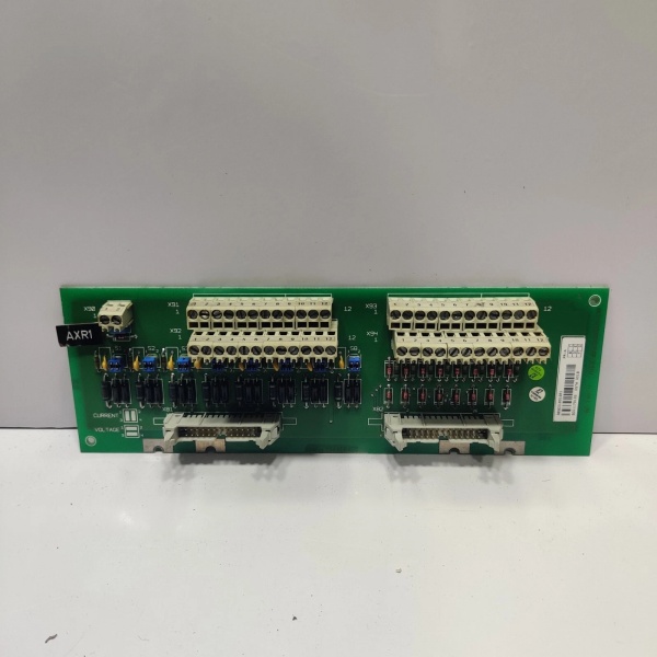
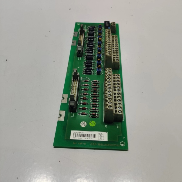
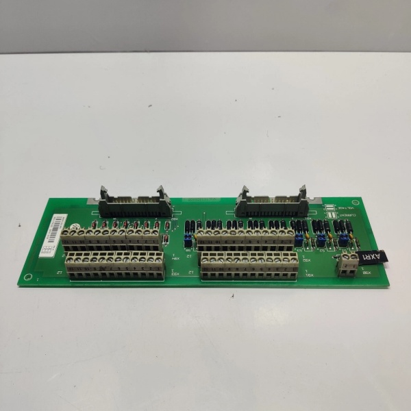
- Model Number: DSTA001B 3BSE018316R1
- Manufacturer: ABB Process Automation
- Digital Inputs: 16 independent channels, 24VDC ±10%
- Input Type: Configurable per module (sink = NPN, source = PNP) via DIP switch
- Response Time: 2ms (typical), 5ms max for signal detection
- Isolation Rating: 500V AC (channel-to-channel; channel-to-backplane)
- Input Current: 4mA (active state), <0.1mA (inactive state)
- Backplane Communication: ABB S800 I/O bus (10Mbps data transfer)
- Power Supply: 24VDC ±10% (from S800 rack power supply; 0.3A max current draw)
- Operating Temperature: -20°C to +60°C (-4°F to +140°F)
- Storage Temperature: -40°C to +85°C (-40°F to +185°F)
- Protection Rating: IP20 (rack-mounted)
- Certifications: UL 508, CE, ATEX Zone 2, IEC 61010-1
- Mounting: Rack-mounted (fits S800 I/O chassis; 1 slot occupancy)
- Status Indicators: Front-panel LEDs (power, module OK, per-channel active status)

ABB DSTA001B 3BSE018316R1
Field Application & Problem Solved
- Safety interlock switches on reactor doors (chemical plants)
- Pump run/status signals in boiler feedwater systems (power plants)
- Valve limit switch feedback in crude distillation columns (refineries)
- Emergency stop (E-stop) signal acquisition in hazardous areas
Installation & Maintenance Pitfalls (Expert Tips)
Rookies leave the module’s DIP switch set to default (sink mode) and connect PNP sensors, resulting in channels that never read “active.” The DIP switch (located on the front panel) has two positions: “SINK” (NPN sensors) and “SOURCE” (PNP sensors). Always match the setting to the sensor’s output type—verify with a multimeter (PNP sensors output 24VDC when active; NPN pull to ground). I’ve fixed 20+ “no signal” faults in a single refinery startup by correcting this setting—this is the #1 mistake with this module.
The module’s screw terminals require 0.5 N·m torque—too loose, and vibration (common near pumps/turbines) causes intermittent signal loss; too tight, and you strip the terminal or damage wire insulation. Use a torque screwdriver (not a regular one) for 2.5mm² (AWG 14) wire. In high-vibration areas (e.g., turbine halls), recheck terminal torque quarterly—this eliminated “random” pump status losses at a 600MW coal plant.
Even with 500V isolation, poor cable routing can introduce noise. Rookies run DI sensor cables alongside power cables (3-phase, 480V) or motor leads, creating EMI-induced false signals. Route DI cables in separate cable trays (minimum 30cm separation from power cables) and use shielded twisted-pair (STP) cable for signals longer than 10 meters. Ground the shield at the sensor end only—grounding both ends creates a ground loop that defeats isolation. I fixed a false E-stop fault at a pharmaceutical plant by rerouting DI cables away from a 480V motor control center.
The DSTA001B is hot-swappable, but rookies yank it out of a live rack without deactivating it in the DCS. This can corrupt the backplane communication bus, causing other modules in the rack to fault. First, use ABB’s Control Builder M to “deactivate” the module (stops backplane communication). Wait 5 seconds for power to discharge, then use the eject lever to remove it. This 10-second step prevents backplane bus lockups—critical in safety-critical loops.
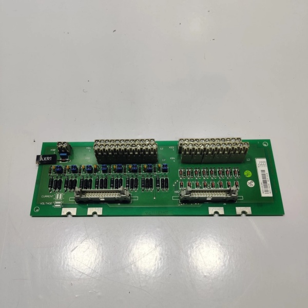
ABB DSTA001B 3BSE018316R1
Technical Deep Dive & Overview
- Isolation Circuitry: Each channel group uses optocouplers to provide 500V AC galvanic isolation, blocking electrical noise and ground loops. This is critical in high-EMI environments (e.g., motor control centers, welding stations) where non-isolated modules fail.
- Signal Conditioning: A dedicated instrumentation amplifier cleans up sensor signals, filtering out high-frequency noise (20kHz+) to ensure reliable detection. The 2ms response time balances speed and noise rejection—fast enough for safety interlocks, slow enough to ignore electrical glitches.
- Backplane Communication: The module communicates with the S800 I/O rack via ABB’s proprietary bus protocol, transferring 16-channel status data to the AC 800M CPU in <1ms. This low-latency ensures real-time control decisions.
- Fault Diagnostics: Front-panel LEDs provide instant status: green “POWER” (module energized), green “OK” (communication with DCS active), and per-channel green LEDs (active signal detected). For remote troubleshooting, the DCS logs faults like “module communication lost” or “overcurrent on channel 8.”


