
Description
Product Core Brief
- Model: CMA114 (OEM P/N: 3DDE300013)
- Brand: ABB Industrial Automation
- Series: S900 Remote I/O System
- Core Function: 16-channel galvanically isolated analog input module for 4–20mA HART transmitters, communicates process values to host DCS via PROFIBUS DP
- Product Type: Intrinsically Safe HART Analog Input I/O Module
- Key Specs: 16 isolated channels | HART 6 multi-variable support | PROFIBUS DP | Ex ia IIC T4 intrinsic safety ratingNote: Discontinued end-of-life field I/O hardware, stocked exclusively as unopened New Surplus inventory.
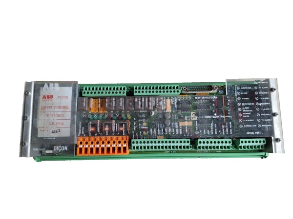
ABB CMA114
Key Technical Specifications
- Compatible Backplane: S900 standard rack backplane; paired terminal base = T9300 series
- Supported Field Signals: 4–20mA two-wire loop-powered HART transmitters
- Channel Count: 16 fully isolated analog inputs, split into two 8-channel galvanic groups
- A/D Conversion Resolution: 15-bit sigma-delta per channel
- Static Accuracy: ±0.08% full scale at 25°C; ±0.15% FS across -40°C to +70°C
- Galvanic Isolation Rating: 2500VAC channel-to-backplane, group-to-group separation
- HART Support: HART 6 protocol, simultaneous PV, SV, TV, QV readback per channel
- Field Loop Supply: Onboard limited 24VDC loop power, max 22mA per channel
- Communication Interface: PROFIBUS DP, 9.6k–12Mbps baud rate range
- Per-Channel Diagnostics: Open wire, short circuit, overrange, HART device offline detection
- Backplane Operating Voltage: 24VDC nominal rack supply; module power draw 3.7W full load
- Ambient Operating Temperature: -40°C minimum to +70°C maximum cabinet ambient
- Hazardous Location Approval: Ex ia IIC T4, FM Class I Div 1/2 Groups A/B/C/D field mounting certified
- PCB Protection: Full acrylic conformal coating for offshore and corrosive refinery environments
- Physical Dimensions: 230mm H × 40mm W × 132mm D; net weight 0.34kg
Product Introduction
This field-mounted I/O module eliminates marshalling cabinet wiring by installing directly near process transmitters. Dual-group galvanic isolation blocks ground loop interference common on long field cable runs.Integrated HART modem circuits pull secondary process variables and device diagnostic codes without external multiplexers, cutting auxiliary hardware count for multi-variable instrument loops in oil & gas and chemical plants.
QA & Testing SOP (Transparency Building)
- Incoming Inspection: Cross-reference serial numbers against ABB OEM batch production logs; inspect PCB for cracked traces, bent backplane edge connectors, and coating delamination; verify factory anti-static packaging seal integrity.
- Live Testing: Mated with matching T9300 terminal base on a bench S900 rack powered by a Fluke 115 regulated 24VDC supply; run 24-hour cyclic 4–20mA ramp testing with simulated open/short fault injection across all 16 channels, plus continuous HART handshake validation with calibrated smart transmitters.
- Electrical Testing: Megger insulation test >10MΩ between each input channel and PROFIBUS backplane bus; confirm loop current limiting activates above 23mA per channel and HART signal coupling meets OEM impedance tolerances.
- Firmware/Config Backup: Capture factory default PROFIBUS address DIP switch positions via high-res photos for field service reference before bench testing.
- Final QC & Packaging: Attach serialized printed test pass tag; seal unit in foam-lined static-shielded bag to protect backplane edge pins during warehouse storage and transit.
Installation Pitfalls & Guide (Engineer to Engineer)
❗ Firmware Rev Compatibility Risk: S900 firmware V2.10 and older releases lack full HART multi-variable logging; upgrade rack interface firmware to V2.30 or newer before module swap to avoid blind transmitter drift faults.❗ DIP Switch Configuration Loss: Capture high-res photos of PROFIBUS address DIP switches on the removed old unit; misconfigured addresses create bus collisions that drop all analog PV values from the DCS host.❗ Wiring Incompatibility: This module’s backplane pinout does not interchange with digital input CMA124 I/O cards; cross-substitution without full T9300 base retermination produces unrecognized bus device faults.❗ Loop Resistance Miscalculation: Combined wire + transmitter resistance exceeding 600Ω collapses full-scale 20mA signals; install inline loop power boosters for field runs longer than 700 meters.❗ ESD Component Damage Risk: Ungrounded technicians have destroyed HART modem ICs during rack card swaps; latent ESD damage creates intermittent loss of secondary variable data that surfaces after 3–4 weeks of continuous runtime.
4-step replacement guide:
- Pre-install: Activate LOTO on 24VDC field transmitter power and PROFIBUS rack power; secure grounded anti-static wrist strap to rack DIN rail ground lug.
- Removal: Document PROFIBUS DIP switch positions via photo; unlatch the module from T9300 terminal base, disconnect all field transmitter wiring channel by channel, extract the unit from rack slot.
- Install: Seat new hardware fully into matching rack slot, replicate all DIP switch address settings from reference photos, reterminate field transmitter wiring to matching terminal base channels, lock module latch fully.
- Power-on Test: Restore rack and field power; access DCS PROFIBUS diagnostic screens to confirm stable primary/secondary PV readings, zero open/short fault flags, and continuous HART device communication across all 16 input channels.
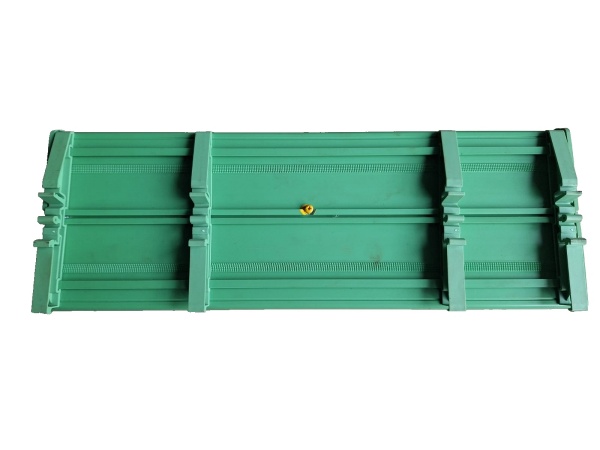
ABB CMA114
FAQ (Frequently Asked Questions)
Q: Can this analog input module operate in redundant rack PROFIBUS configurations?A: The hardware does not include dual mirrored signal paths for native channel redundancy. Redundant process measurement requires dual independent + T9300 pairs wired parallel to field transmitters; single module slots cannot deliver 1oo2 fault tolerance for SIL-rated critical control loops.Q: Does the module support hot-swapping while the rack PROFIBUS bus remains energized?A: The module can be extracted from the live rack slot, but all external field transmitter wiring must be fully disconnected via LOTO before removal. Live field power disconnection induces voltage transients that damage the onboard HART filter circuits on the PCB.Q: What warranty coverage applies to bench-tested surplus stocked units?A: All inventory units carry a 12-month functional warranty covering factory PCB, galvanic isolation, and HART modem circuit defects. Damage from field surge overload, misconfigured PROFIBUS DIP switches, or ungrounded ESD handling is excluded from all coverage terms.Q: Is there a direct drop-in modern replacement for this discontinued I/O hardware?A: ABB’s current S800 Remote I/O series offers equivalent HART analog input functionality, but full field harness retermination and DCS PROFIBUS communication logic revalidation is mandatory; backplane pinout and HART polling timing do not match for unmodified direct swap.Q: What fault isolation do the two independent 8-channel galvanic groups provide during field wiring shorts?A: Each 8-channel bank uses separate isolation and current limiting circuits; a shorted transmitter wire only disables one channel within its group, leaving the remaining 15 analog measurement loops fully operational for process monitoring.Q: Can low-level TC/RTD sensors be wired directly to this module’s input terminals?A: No. The onboard signal conditioning circuitry is hardwired exclusively for 4–20mA current transmitters. Thermocouple and RTD low-level millivolt signals require separate CMA134 temperature input modules with dedicated cold-junction compensation hardware.Q: Can multiple HART transmitters be wired in parallel to a single input channel terminal?A: Not permitted. The intrinsic safety loop power supply is sized for one transmitter per channel only; parallel multi-drop wiring violates Ex ia safety ratings and triggers persistent overcurrent fault alarms.


