
Description
Product Introduction
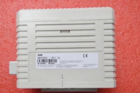
The ABB 3BSE071501R1 is a CEX-Bus interconnection unit designed to split a single bus segment into two independent paths, extending cable runs up to 200 meters. It acts as the physical bridge between redundant PM8xx CPUs and remote I/O clusters in large-scale 800xA deployments.
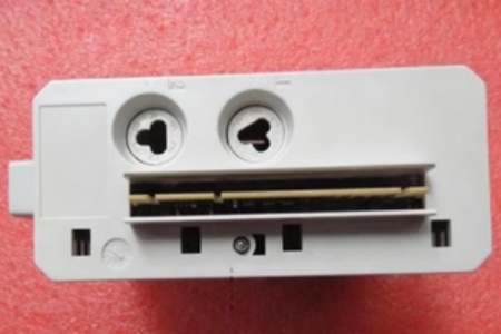
This unit supports transparent transmission of RCU (Redundancy Control Unit) links, ensuring the standby CPU stays synced within microseconds. It mounts on standard 35 mm DIN rail and draws power directly from the CEX-Bus, though an external 24 Vdc tap is available for redundant power schemes. Operating temp holds steady from 5 to 55 °C.
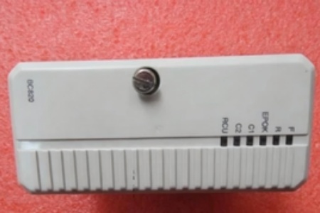
ABB BC820K01 3BSE071501R1
Key Technical Specifications
- System Compatibility: AC 800M (PM858, PM862, PM866/A, PM891)
- Bus Interfaces: CEX-Bus (Primary) + RCU-Link (Control/Data)
- Max Segment Length: 200 m (62.5/125 µm MM Fiber or STP)
- Max CEX Nodes: 6 Interfaces per BC820 unit
- Supply Voltage: 24 Vdc (Primary: Via CEX-Bus | Aux: Screw Terminals)
- Power Consumption: Typ. 2.9 W (120 mA @ 24 Vdc)
- Indicators: PWR, BUS (Activity), ERR (Fault)
- Mounting: 35 mm DIN Rail (EN 60715)
- Dimensions: 59 mm (W) x 185 mm (H) x 127.5 mm (D)
- Weight: Approx. 0.77 kg – 1.4 kg
- Protection: IP20 (Chassis), Conformal Coated PCB
Quality Control Process (Engineer’s Perspective)
- Incoming Verification: Match the 3BSE071501R1 label to the silkscreen on the ABB PCB. Check the RJ45/DB9 ports for bent pins. Inspect the DIN clip spring tension; weak springs cause bus drops in vibrating cabinets.
- Live Functional Test: Rig in a test rack with a PM866A pair. Generate RCU sync traffic. Monitor the BUS LED blink rate; we look for sub-10 µs latency on the link—any jitter here desyncs the hot-standby.
- Electrical Parameter Test: Check the external 24 Vdc screw terminal impedance with a Fluke 115. Megger the bus shield to chassis ground at 500 V; resistance must stay >10 MΩ to prevent ground loop noise.
- Firmware Verification: Query the hardware ID via Control Builder. Photograph the unit’s MAC address label on the underside—well, technically it’s a bus device, but asset tracking needs this for the CMDB.
- Final QC & Packaging: Clean the contact edges. Wrap in conductive ESD foam with desiccant. Label “QC Passed – Link Sync Verified” with the date.
Replacement Pitfall Guide
❗ Controller Generation: The ABB 3BSE071501R1 is strictly for PM858/PM866/PM891 processors. Do not pair it with older PM856 or AC 800M High Integrity (HI) CPUs; the RCU link timing is incompatible and triggers “Redundancy Lost” faults.
❗ Termination Resistors: Forgetting the TB850 terminator at the end of the second CEX segment causes signal reflections. This manifests as intermittent “Node Missing” errors during high I/O scan loads.
❗ External Power Jumpers: If using the auxiliary 24 Vdc input (terminals L+/L-), ensure the internal jumper (JP1/JP2) is set correctly. Leaving it on “Bus Powered” with a connected external PSU can back-feed 24 Vdc into the CPU backplane—bad news.
❗ Cable Type Mismatch: The RCU-Link requires specific crossover pinouts (T568A to T568B). Using a standard patch cable kills the redundancy sync between the primary and backup CPU.
❗ ESD to Ports: The RJ45 interfaces are static-sensitive. Discharge to the DIN rail before plugging cables—though your mileage may vary on cabinet grounding quality in older plants.
Keep these in mind and you’ll cut 90% of rework time.
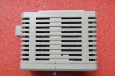
ABB BC820K01 3BSE071501R1
Compatibility Matrix & Benchmarks
- ABB 3BSE071501R1 → ABB BC810 : Needs Adaptation — BC810 lacks full RCU-Link transparency; requires logic review for PM866+
- ABB 3BSE071501R1 → ABB PM866A (TU852) : Direct — Native support for segmented CEX topology
- ABB 3BSE071501R1 → ABB CI854A (Profibus) : Incompatible — BC820 is infrastructure; CI854 is a field protocol interface
- RCU Sync Time: < 10 µs (Typical redundancy switchover)
- Segment Span: 200 m (Max per CEX leg)
- Bus Speed: 1.25 Mbps / 10 Mbps (CEX Layer dependent)


