
Description
Hard-Numbers: Technical Specifications
- Measurement Principle: Thermal Conductivity Detector (TCD) with glass-coated platinum resistor
- Measurement Components: H2 in N2, H2 in Air, SO2 in N2, SO2 in Air
- Smallest Measurement Range: 0-0.5% H2 in N2, 0-0.5% H2 in Air, 0-1.5% SO2 in N2, 0-1.5% SO2 in Air
- One Measurement Range: Per measuring component (Caldos25 has one range per component, not switchable like Caldos27)
- Sample Gas Flow Rate: Max. 100 l/h
- Sample Gas Temperature: +5 to +50°C
- Sample Gas Inlet Pressure: Max. 1100 hPa absolute (100 hPa gauge)
- Pressure Drop at Flame Arrester: Approx. 130 hPa at 60 l/h flow
- Response Time (T90): Not specified in search results; glass-coated design prioritizes corrosion resistance over speed
- Power Consumption: Max. 187 VA
- Supply Voltage: 100-240 VAC ±10%, 50/60 Hz, 2.2 A max
- Housing (AO2040): Wall-mount, IP20 standard, IP54 with connection box
- Housing (AO2040-CU Ex): Flameproof enclosure ‘d’ per EN 60079-1, IP65 with O-ring seal
- Operating Temperature (with electronics module): Caldos25 +5 to +45°C; without electronics module +5 to +50°C
- Storage Temperature: -25 to +65°C
- Relative Humidity: Max. 75%, slight condensation allowed
- System Bus Length: Max. 350 meters linear
- Communication Interfaces: Ethernet 10/100/1000BASE-T, Modbus (RS485/RS232 optional), Profibus optional
- Analog Outputs: 2-way or 4-way analog output modules available (4-20 mA)
- Digital I/O: 4 digital inputs/outputs on digital I/O modules
- Weight: AO2040 central unit approx. 20 kg; Caldos25 module weight not specified
- Materials in Contact with Sample Medium: Stainless steel 1.4305 (AISI 303), glass, flame arrester stainless steel 1.4571 (AISI 316Ti)

The Real-World Problem It Solves
You’re running a chlorine electrolysis cell and need to monitor hydrogen contamination in the chlorine stream. Conventional thermal conductivity detectors corrode rapidly in HCl/Cl2 environments, causing drift and frequent sensor replacement. The CALDOS A25 uses a glass-coated resistor that withstands corrosive gases, eliminating sensor burnout and reducing maintenance cycles in aggressive chemical processes.
Where you’ll typically find it:
- Chlor-alkali plants measuring hydrogen contamination in chlorine gas streams (H2 in Cl2 measurement)
- Non-ferrous metal smelters monitoring SO2 concentration in off-gas streams for sulfur recovery
- Ammonia cracking units monitoring hydrogen concentration in nitrogen or air mixtures
- Chemical production processes involving corrosive gas mixtures requiring continuous H2 measurement
Bottom line: This analyzer survives where standard TCDs fail, cutting sensor replacement costs and downtime in corrosive gas applications.
Hardware Architecture & Under-the-Hood Logic
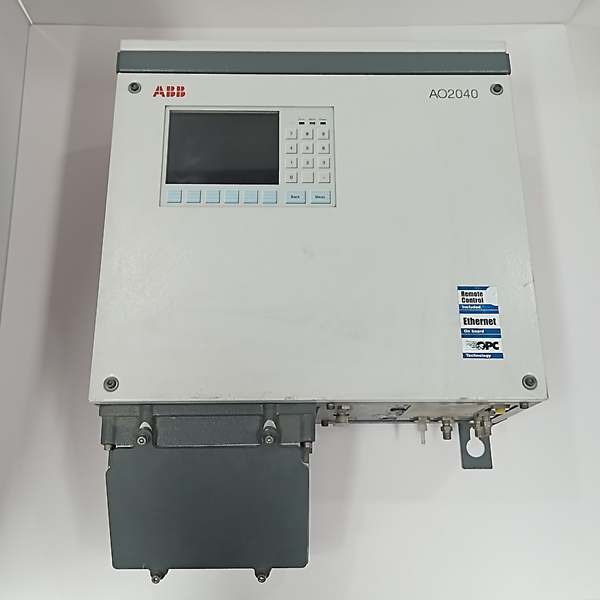
The AO2040 central unit houses the system controller and power supply, communicating with analyzer modules via the system bus. The CALDOS A25 (Caldos25) module contains the thermal conductivity measurement cell and its own processor. Unlike the silicon sensor in Caldos27, Caldos25 uses a glass-coated platinum resistor for corrosion resistance. The sample gas passes through the measuring cell, and the thermal conductivity difference between the reference gas and sample gas changes the resistor temperature, which is converted to a concentration reading.
Internal signal flow:
- Sample gas enters through flame arrester (stainless steel 1.4571) at 15-100 l/h flow rate
- Gas passes through pressure regulator maintaining max. 100 hPa gauge pressure
- Sample flows through thermal conductivity cell containing glass-coated platinum resistor
- Resistor temperature changes based on thermal conductivity difference between sample and reference
- Wheatstone bridge circuit converts resistance change to voltage signal
- Module processor digitizes signal and performs linearization
- Measured value transmitted via system bus to central unit controller
- Central unit processes data with cross-sensitivity compensation and outputs via analog/digital interfaces
- Calibration can be performed manually or automatically via pneumatic module with test gas solenoids
- For Zone 2 applications with flammable gases, purge gas (N2) creates positive pressure curtain around sample cell
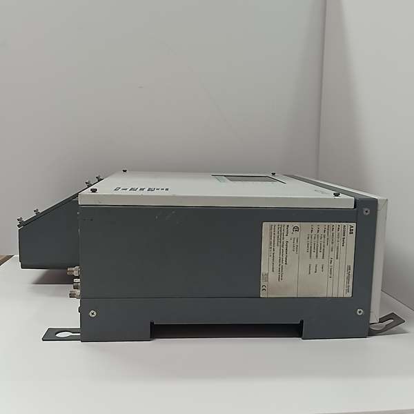
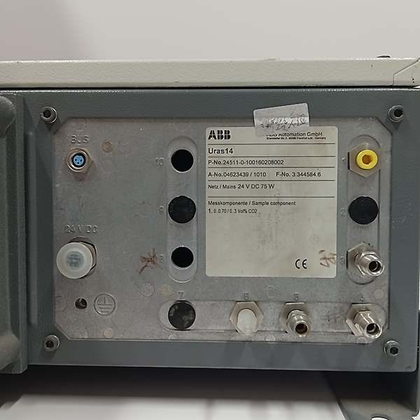
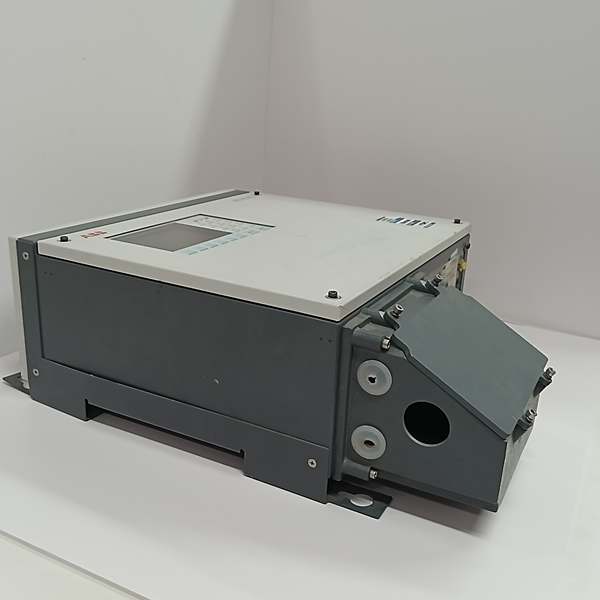
ABB АО2040/CALDOS A25
Field Service Pitfalls: What Rookies Get Wrong
Ignoring Purge Gas Requirement for Corrosive ApplicationsNew techs install CALDOS A25 in Zone 2 flammable gas service without purge gas flow. Sample gas leaks into analyzer housing, and without the inert gas curtain, explosive atmosphere forms inside the enclosure.
- Field Rule: For Zone 2 applications with flammable sample gases, install N2 purge gas at 15-40 l/h. The purge curtain must maintain positive pressure ≥0.5 hPa above sample gas pressure at all times.
Using Water-Cooled Sample Gas Without Proper Condensate RemovalRunning sample gas with high moisture content directly into the CALDOS A25 causes condensation on the glass-coated resistor. Water droplets create erratic readings and thermal shock cracks the glass coating over time.
- Quick Fix: Install a sample gas cooler (SCC-C) or condensate trap before the analyzer. Keep sample gas temperature above dew point (minimum +5°C) entering the analyzer.
Calibrating with Cross-Contaminated GasesTechs use the same calibration gas bottles for multiple analyzer types without checking cross-sensitivity. Residual gases from previous calibrations contaminate the thermal conductivity cell, causing baseline drift.
- Field Rule: Use dedicated, clean calibration gas cylinders for CALDOS A25. Verify gas composition matches the measured component’s background gas (N2 vs. air). Never use calibration gas intended for oxygen analyzers.
Exceeding Flame Arrester Pressure DropOperators crank sample gas flow to 80-100 l/h to improve response time. The 130 hPa pressure drop across the flame arrester causes sample cell pressure to exceed specifications, damaging the glass-coated resistor seal.
- Quick Fix: Maintain sample gas flow at 20-60 l/h maximum. If faster response is required, relocate analyzer closer to sample tap or use smaller diameter tubing to reduce transport delay instead of increasing flow.
Missing Ground Connection on Flame ArresterThe stainless steel flame arrester (1.4571) builds static charge from high-velocity gas flow. Without grounding, electrostatic discharge arcs across the arrester mesh, igniting flammable sample gases in Zone 2 applications.
- Field Rule: Bond the flame arrester housing to plant ground with a solid copper strap. Verify continuity before commissioning. Check ground resistance annually.
Using Caldos25 Switching Range Configuration like Caldos27Techs try to configure dual measurement ranges per component in Caldos25 software menus, confusing it with Caldos27. The software rejects the configuration or defaults to single range, wasting hours troubleshooting a non-existent fault.
- Field Rule: Caldos25 has one measurement range per component. If you need range switching, use Caldos27 (silicon sensor with dual ranges) or install two Caldos25 modules in parallel.
Neglecting Glass-Coated Resistor Warm-Up TimeNew personnel power up the analyzer and start calibration immediately. The glass-coated thermal resistor requires 30-60 minutes to stabilize at operating temperature. Calibration performed during warm-up shows zero drift and requires recalibration once stabilized.
- Field Rule: Allow minimum 1-hour warm-up period after power-up before performing calibration. Monitor the analyzer status indicator for “Ready” state before initiating calibration sequence.
Commercial Availability & Pricing Note
Please note: The listed price is for reference only and is not binding. Final pricing and terms are subject to negotiation based on current market conditions and availability.


