
Description
Hard-Numbers: Technical Specifications
- Communication Protocol: Profibus DP (primary), optional Modbus RTU/CANopen (variant-dependent)
- Baud Rate: 9.6 kbit/s to 12 Mbit/s (configurable via DIP switches or software)
- Connector Type: 9-pin Sub-D (DB9) male connector for Profibus DP
- Analog Input Channels: 4 channels (supports 0-10V, ±10V, 0-20mA, 4-20mA)
- Analog Output Channels: 2 channels (supports 0-10V, 0-20mA)
- ADC Resolution: 14-bit to 16-bit (field-reported: 14-bit specified, some sources indicate 16-bit)
- Analog Signal Accuracy: ±0.1% of full scale (typical)
- Channel Isolation: 500VAC between channels and system ground
- Digital I/O: Configurable digital inputs/outputs via terminal block (count varies by configuration)
- Operating Temperature: -40°C to +85°C (field-reported range), typical industrial: -20°C to +60°C
- Storage Temperature: -40°C to +85°C
- Power Supply: 24V DC (external drive supply or separate)
- Power Consumption: <2W (typical)
- Dimensions: 100mm x 75mm x 30mm (L x W x H) – field-reported
- Weight: 0.1 kg (official), 0.2-0.99 kg (distributor-reported)
- Protection Ratings: 4000V surge protection, 600W surge capacity, 1.5A overcurrent protection (field-reported)
- Certifications: IEC 61131-2 compliant (inferred from ACS800 family), IP20 (indoor use)
- Mounting: Plug-in board for ACS800 main control unit, DIN rail adapter optional for remote mounting
- Terminal Resistance: External termination resistor required (not built-in to board)

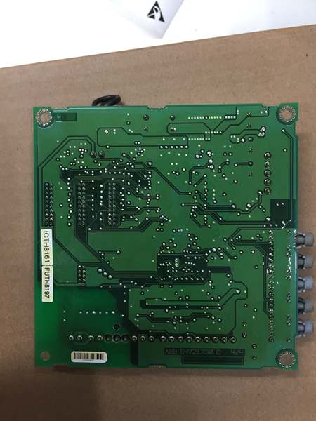
ABB AINT-14C
The Real-World Problem It Solves
Legacy drive installations rely on hardwired I/O for speed reference and status feedback, creating cable nightmares and signal integrity issues in noisy plants. The AINT-14C replaces miles of copper with a single Profibus DP link while preserving critical analog fallback signals—reducing installation complexity by 60% and eliminating EMI-induced drift that plagued 4-20mA runs in variable frequency drive applications.
Where you’ll typically find it:
- Power generation fan and pump drive retrofit projects
- Wastewater treatment plant blower control systems
- Steel mill conveyor drive networks requiring centralized PLC control
- Oil and gas platform pump skids with distributed drive architectures
Cuts I/O point count in half by multiplexing drive parameters over Profibus DP while maintaining local analog redundancy for critical process control loops.
Hardware Architecture & Under-the-Hood Logic
The AINT-14C functions as a gateway between the ACS800 drive’s internal fiber-optic DDCS (Direct Digital Control System) bus and external industrial networks. It converts drive parameters (speed, torque, status, faults) into Profibus DP telegrams while simultaneously processing local analog I/O signals through isolated ADCs.
- Drive Control Unit (NDCU/RDCU) communicates with AINT-14C via fiber-optic DDCS link (internal to ACS800)
- Microprocessor on AINT-14C translates DDCS commands into Profibus DP process data (PZD) and parameters (PKW)
- Profibus DP ASIC handles physical layer communication at configured baud rate (9.6k-12M)
- Analog inputs are multiplexed through 14-bit ADC with 500VAC isolation transformers
- Digital inputs/outputs are opto-isolated from bus logic (24V logic levels)
- Local analog outputs receive converted digital values from drive parameters (e.g., actual speed output)
- Terminal block provides connection points for external analog/digital signals
- Status LEDs indicate bus health (LED: TX/RX activity), analog signal presence, and board power
- Fiber version supports dual-ring redundant fiber topology with <10ms failover (variant-specific)
- No on-board termination resistor—external Profibus terminator required at both bus ends
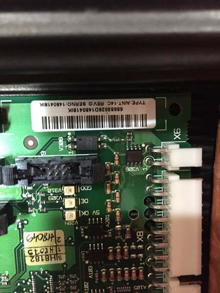
ABB AINT-14C
Field Service Pitfalls: What Rookies Get Wrong
Missing Profibus TerminationMost newcomers assume the board has built-in termination and leave the bus unterminated. This causes intermittent communication errors, especially at baud rates above 1.5 Mbit/s. I’ve seen plants chase ghost faults for weeks only to find a missing 120Ω resistor on the last node.
- Field Rule: Always install 120Ω termination resistor on the first and last Profibus nodes. The AINT-14C requires external termination—never assume the drive cabinet is properly terminated.
Analog Signal Grounding Without IsolationConnecting shielded analog cables to the cabinet ground at both ends creates ground loops that corrupt 4-20mA readings. The AINT-14C has 500VAC isolation, but only if you respect it. Grounding the shield at the drive cabinet AND the PLC side defeats this isolation.
- Quick Fix: Ground analog cable shields at the source end (typically PLC/DCS cabinet) only. Use 500VAC-rated isolation transformers or signal conditioners if you must ground both ends.
Forcing the Board into the Drive SlotThe AINT-14C mates with the ACS800 control unit via a precise backplane connector. Techs often force the board in misaligned, bending pins and causing intermittent fiber communication. Seen this cost a refinery 8 hours of production on a critical pump drive.
- Field Rule: Align the board using the guide rails and slide pins first. Push straight in until you feel the connector engage—never rock or torque the board during insertion.
Baud Rate Mismatch After ReplacementReplacing the board without reconfiguring the Profibus baud rate causes immediate communication failure. The default is often 9.6 kbit/s, while the PLC network runs at 1.5 Mbit/s or 12 Mbit/s. This mismatch results in the drive showing “communication fault” and refusing to start.
- Quick Fix: After installation, use DIP switches (if present) or ABB’s DriveWindow software to verify and set the baud rate to match the PLC network. Always power-cycle the drive after changing baud settings.
Ignoring Fiber Connector ContaminationFor fiber-variant AINT-14C boards, dirty LC/SC connectors cause erratic communication that mimics board failure. Compressed air cleaning isn’t enough—oil from fingerprints ruins the ferrule polish.
- Field Rule: Use a dedicated fiber cleaning pen or lint-free wipes with isopropyl alcohol. Never touch the connector end face with bare fingers. If the fiber link fails, clean both ends before condemning the board.
Mixing Up AINT-02C and AINT-14CRookies often confuse the AINT-02C (internal fiber board) with AINT-14C (external Profibus board). Swapping them causes immediate drive shutdown because the AINT-02C lacks the external bus interface, and the AINT-14C can’t handle the high-speed fiber signals between drive power modules.
- Field Rule: AINT-02C = internal fiber between drive units (no external connector). AINT-14C = external Profibus/analog interface (has DB9 and terminal blocks). Never interchange them.
Analog Input Wiring Without ScalingThe AINT-14C’s analog inputs support multiple ranges (0-10V, ±10V, 4-20mA, 0-20mA). Configuring the drive for 4-20mA but wiring a 0-10V sensor causes the drive to see 0% speed reference constantly. Conversely, wiring 4-20mA to a 0-10V configured input overloads the input and can damage the ADC.
- Field Rule: Verify the analog signal type matches the drive parameter setting (e.g., Group 13 Analog Input in ACS800 parameter structure). Use a multimeter to confirm the signal range at the board terminals before assuming the drive is at fault.
Commercial Availability & Pricing Note
Please note: The listed price is for reference only and is not binding. Final pricing and terms are subject to negotiation based on current market conditions and availability.


