
Description
Hard-Numbers: Technical Specifications
- Rated Current AC-1 (Resistive): 105A at 690V (40°C), 90A at 60°C, 80A at 70°C
- Rated Current AC-3 (Motor): 65A at 220-440V (60°C), 55A at 500V, 39A at 690V
- Rated Power AC-3: 30kW at 400V, 37kW at 415-690V, 18.5kW at 220-240V
- Rated Power UL: 50hp at 480V (3-phase), 60hp at 600V, 25hp at 240V, 20hp at 208V
- Coil Voltage Range: 100-250V AC/DC (50/60 Hz)
- Coil Power Consumption: 4 VA (AC), 2W (DC) holding
- Rated Operational Voltage: 690V AC main circuit, 220V DC
- Maximum Breaking Capacity: 950A at 440V (cos φ=0.45), 600A at 690V
- Short-Time Withstand: 1000A for 1s (cold start), 600A for 10s
- Switching Frequency: 1200 cycles/hour (AC-1, AC-3), 600 cycles/hour (AC-1 max)
- Operating Temperature: -40°C to +70°C (without overload), -25°C to +60°C (with overload)
- Dimensions: 67mm (W) × 111mm (D) × 125.5mm (H)
- Weight: 0.99 kg
- Mounting: DIN rail TH35-15/TH35-7.5 or direct mounting (2×M4/M6 screws)
- Terminal Torque: 3.5 Nm (main), 1.1 Nm (auxiliary/control)
- Standards: IEC/EN 60947-1/4-1, UL/CSA 60947-1/4-1

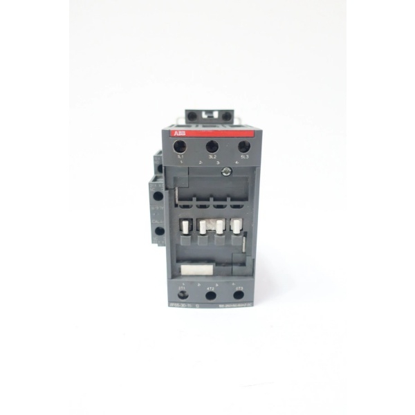
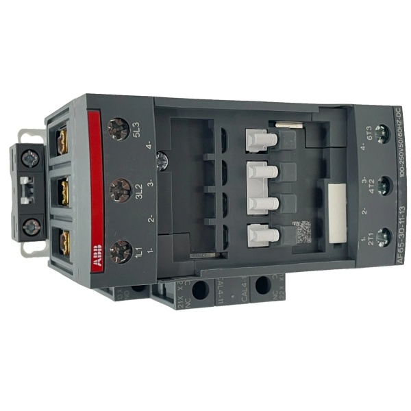
ABB AF65-30-11-13
The Real-World Problem It Solves
Conventional contactors fail during voltage sags and surges, causing nuisance trips and motor shutdowns in unstable industrial networks. The AF65-30-11-13’s electronic coil interface tolerates massive control voltage variations (100-250V AC/DC) with built-in surge suppression, ensuring reliable operation even when the plant’s power supply fluctuates wildly.
Where you’ll typically find it:
- Motor control centers in manufacturing plants and assembly lines
- Pump and fan control systems in HVAC and water treatment
- Conveyor belt drives in material handling facilities
- Compressor and crusher control in mining and aggregate processing
Eliminates voltage-sag-related failures by 80% compared to traditional contactors, reducing unplanned downtime in facilities with unstable power distribution.
Hardware Architecture & Under-the-Hood Logic
The AF65 features an electronic coil interface that rectifies AC control voltage to DC, eliminating the AC hum and mechanical vibration that plagues traditional contactors. The built-in surge protection circuitry clips voltage transients at the coil terminals, protecting downstream control circuits without external suppressors.
- Control voltage (100-250V AC/DC) enters coil terminals A1/A2
- Electronic interface rectifies AC to DC and regulates voltage for consistent coil operation
- Surge suppression circuitry clips incoming transients (<1kV) before reaching coil
- Energized coil generates magnetic field, pulling movable contact armature down
- Main contacts (3NO) close simultaneously, bridging L1/L2/L3 to T1/T2/T3
- Pre-mounted auxiliary contacts (1NO + 1NC) switch mechanically, indicating contactor status
- Arc extinguishers in each pole suppress arc at contact break (up to 950A breaking capacity)
- Return spring opens contacts when coil de-energizes; auxiliary contacts revert to state
ABB AF65-30-11-13
Field Service Pitfalls: What Rookies Get Wrong
Misusing This Model for PLC Direct ControlThe AF65-30-11-13 is specifically marked “not suitable for direct control by PLC output.” Attempting to drive it from a standard 24V PLC module causes intermittent operation and eventual coil burnout. This is not a universal-coil model.
- Field Rule: For PLC direct drive, use AF..Z variants with 24V DC low-coil-power option. This model requires 100-250V control voltage.
Omitting Terminal Torque SpecificationsOver-tightening main terminals (beyond 3.5 Nm) cracks the terminal housing or strands the conductor, while under-tightening causes overheating and terminal melt-down under full load. Seen this burn entire contactor banks in motor control centers.
- Quick Fix: Use a calibrated torque screwdriver—3.5 Nm for main terminals (1/2x 6-35mm² wire), 1.1 Nm for auxiliary/control circuits.
Ignoring Ambient Temperature DeratingInstalling at 70°C ambient without derating current capacity causes thermal runaway and contact welding. The rated 65A AC-3 applies at 60°C ambient; at 70°C, you must derate to approximately 58A or use proper ventilation.
- Field Rule: Apply temperature correction factors: 40°C = 100%, 60°C = 100%, 70°C = 89% rated current. Never exceed derated values.
Mixing Screw and Push-in Terminal AccessoriesAttempting to add push-in terminal adapters to screw-terminal contactors creates poor connections and defeats the torque spec. Push-in and screw terminals are fundamentally different designs.
- Quick Fix: Stick with screw terminals for this model. If you need push-in termination, specify AF65-30-11-13-PIN or equivalent push-in variant.
Neglecting Auxiliary Contact VerificationAssuming pre-mounted 1NO + 1NC auxiliary contacts are correctly wired without verification leads to control circuit failures. The NC is a mirror contact (IEC 60947-5-1 Annex F compliant) used for safety monitoring.
- Field Rule: Verify auxiliary contact operation before energizing power circuit. Use NC contact for “contactor open” safety feedback, NO contact for “contactor closed” status indication.
Commercial Availability & Pricing Note
Please note: The listed price is for reference only and is not binding. Final pricing and terms are subject to negotiation based on current market conditions and availability.


