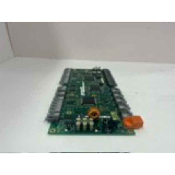
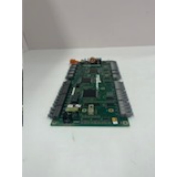
Description
Component Snapshot At-a-Glance
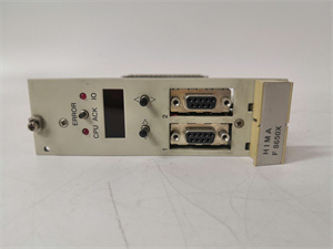
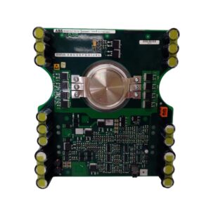
- Model: 3BHE004573R0143 (UFC760 BE143)
- Alt. P/N: 3BHE004573R0043, LXEB2000P0
- Product Series: ABB UFC760, compatible with AC 800F/800xA, ACS 6000/880 MV Drives
- Hardware Type: Isolated analog + digital I/O communication bridge board
- Key Feature: Combined 12x digital + 4x analog channels with 500 VAC isolation and dual Profibus ports
- Primary Field Use: Interface field sensors and actuators to DCS/PLC for generator excitation, MV drive control, and process safety loops.
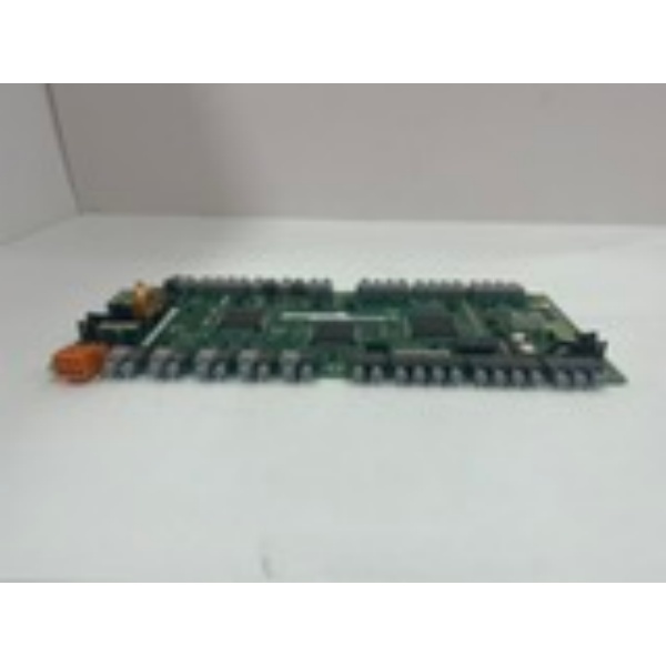
3BHE004573R0143
Hard-Numbers: Technical Specifications
- Protocol Support: Profibus DP (dual), Modbus RTU, EtherNet/IP
- Port Count: 12x digital in (24 VDC), 4x analog in (0–10 V / 4–20 mA), 6x relay out (5 A @ 250 VAC)
- Baud Rate: Profibus up to 12 Mbps; Ethernet 1 Gbps
- Isolation Rating: 500 VAC channel-to-channel, 2500 VAC channel-to-backplane
- Operating Temperature: -20 °C to +60 °C (derate above +55 °C)
- Power Draw: 7 W typical, 24 VDC ±20% (100–240 VAC option available)
- Analog Accuracy: ±0.1% FS, 16-bit resolution
- Safety Rating: SIL3 per IEC 61508, PL e / Cat.4
- Storage Temperature: -40 °C to +85 °C
- Mounting: EN 50022 DIN rail, hot-swap capable
The Real-World Problem It Solves
Field signals mix analog (4–20 mA) and discrete (24 VDC) levels, often in high-noise MV drive and generator rooms. Separate I/O cards add cost and cabinet space; non-isolated boards cause ground loops and signal drift.
Where you’ll typically find it:
- Generator excitation panels for voltage feedback (4–20 mA) and breaker status (24 VDC)
- ACS 6000/880 MV drive cabinets for motor temperature, vibration, and interlock monitoring
- Process SIS/ESD systems requiring SIL3-rated analog + discrete input consolidation
This board cuts cabinet clutter, maintains signal integrity in dirty power environments, and meets safety standards for critical control loops.
Hardware Architecture & Under-the-Hood Logic
Onboard 32-bit ARM processor handles I/O sampling, scaling, and bus communication. All channels use opto-couplers; analog inputs have dedicated sigma-delta converters.
- Field analog (4–20 mA/0–10 V) and discrete (24 VDC) signals land on front screw terminals.
- Opto-isolators block common-mode noise; analog signals pass to 16-bit ADCs.
- Processor filters, scales, and linearizes analog data; debounces digital inputs.
- Data transmits over dual Profibus DP links (redundant) or Ethernet to the main controller.
- Relay outputs activate interlocks/alarms; front LEDs indicate power, comms, and channel status.

3BHE004573R0143
Field Service Pitfalls: What Rookies Get Wrong
Overloading Relay Outputs
Technicians switch 120/240 VAC loads directly to the 5 A relays. Arcing burns contacts, causing intermittent faults and FAULT light triggers.
- Field Rule: Use relays only for control signals. Install external contactors for loads >3 A or inductive circuits.
Incorrect Analog Wiring (2-Wire vs. 4-Wire)
Rookies wire 2-wire 4–20 mA transmitters to 4-wire analog inputs. This creates voltage drop, signal drift, and noisy readings.
- Quick Fix: For 2-wire transmitters, jump +24 VDC to the transmitter supply terminal; connect signal return to board common.
Ignoring Hot-Swap Precautions
Techs yank the card live without checking bus status. Backplane voltage spikes damage the processor, bricking the board.
- Field Rule: Disable the Profibus master port first. Wait 10 seconds for bus quiescence before insertion/removal.
Commercial Availability & Pricing Note
Please note: The listed price is for reference only and is not binding. Final pricing and terms are subject to negotiation based on current market conditions and availability.