
Description
Hard-Numbers: Technical Specifications
- Processor Type: ARM Cortex-A8 (per HESG324436R3/A variant)
- Processor Speed: 600 MHz (per HESG324436R3/A variant)
- System Memory: 512 MB DDR3 RAM
- Storage Memory: 2 GB eMMC
- Operating System: Embedded real-time OS
- Power Supply Voltage: 12-48 V DC (wide-range redundancy)
- Power Consumption: Typical 5-10 W (estimated based on S800 I/O family)
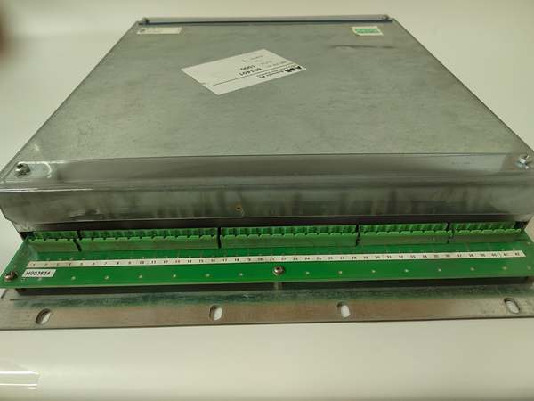
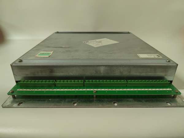
- Power Connection: Removable terminal block with screw connection
- Protection Against Reverse Polarity: Yes
- Communication Interfaces: ModuleBus (internal), Ethernet (10/100 Mbit), RS-232/RS-485/RS-422 (software configurable via COM1)
- I/O Capacity: Supports up to 64 I/O modules via ModuleBus expansion
- ModuleBus Speed: High-speed serial communication (4-108 ms scan cycle typical)
- Hot-Swap Capability: Yes (ModuleBus lock switch required for relay outputs)
- Operating Temperature: -20°C to +60°C (per HESG324436R3/A variant)
- Storage Temperature: -40°C to +85°C
- Operating Humidity: 5% to 85% relative humidity, non-condensing
- Ingress Protection: IP20 (DIN-rail or cabinet mounting)
- Vibration Resistance: G3 severity level compliance (per S800 I/O family)
- Shock Resistance: ±50 g, 11 ms, 3 pulses per axis (EN 60068-2-27)
- EMC Compliance: EN 61000-6-4, EN 55011 Class A
- ESD Immunity: 8 kV air discharge, 4 kV contact discharge (EN 61000-4-2)
- Radiated RF Immunity: 80 MHz-1 GHz, 10 V/m; 1.4-2 GHz, 3 V/m (EN 61000-4-3)
- Burst Immunity: ±2 kV DC power port, ±1 kV signal line (EN 61000-4-4)
- Surge Immunity: ±0.5 kV DC power port (line-to-earth), ±1 kV signal line (EN 61000-4-5)
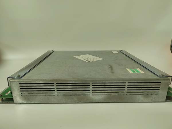
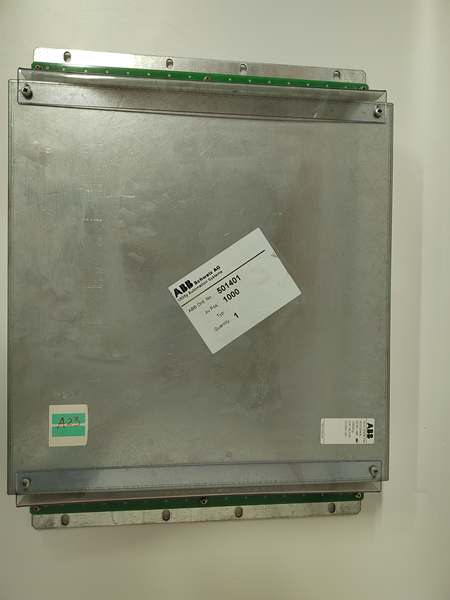
- Dimensions: 125 mm × 80 mm × 40 mm (per HESG324436R3/A variant)
- Weight: 0.5 kg (per HESG324436R3/A variant)
- Mounting Type: DIN-rail (35mm) or cabinet installation via ModuleBus rack
- LED Indicators: Power (PWR), Run (R), Fault (F), ModuleBus communication status
- MTBF: ≥150,000 hours (estimated based on S800 I/O family)
- Certifications: IEC 61131-2, CE, ATEX (intrinsic safety variants available)

ABB HESG324430R11/B
The Real-World Problem It Solves
Centralized control architectures require miles of field wiring to remote sensors and actuators, creating signal integrity problems, high installation costs, and maintenance nightmares in large process plants. The 216GD61A distributes I/O processing to the field via ModuleBus, reducing cable runs by up to 70% while providing hot-swappable modules and redundant power that keep critical processes running during I/O replacement or power failures.
Where you’ll typically find it:
- Distributed I/O stations in petrochemical refining and chemical processing plants
- Remote I/O nodes for water treatment facilities with widely dispersed sensor arrays
- Field I/O clusters in steel mills and metal processing operations
- Process automation islands in power generation and pulp & paper mills
Eliminates single points of failure in I/O infrastructure through redundant power and hot-swap capability, reducing planned and unplanned downtime by up to 50% compared to centralized I/O architectures.
Hardware Architecture & Under-the-Hood Logic
The 216GD61A functions as a ModuleBus master or slave processor within the S800 distributed I/O system, managing communication between upstream controllers (AC800M, Freelance) and downstream I/O modules via the high-speed ModuleBus backplane. The ARM-based processor executes I/O scanning, signal conditioning, and diagnostic functions independently of the main controller, ensuring deterministic response times for process control applications.
- Power input (12-48 V DC) enters via removable 3-pin terminal block
- Reverse polarity protection circuit prevents damage from incorrect wiring
- DC-DC converter supplies regulated 5V logic power and 3.3V core voltage
- ARM Cortex-A8 600MHz processor boots embedded OS from 2 GB eMMC storage
- 512 MB DDR3 RAM loads I/O configuration, diagnostic routines, and communication stacks
- ModuleBus interface handles high-speed serial communication with I/O modules (4-108 ms scan cycle)
- Ethernet port (10/100 Mbit) provides connection to upstream controllers (AC800M, Freelance)
- Serial port (COM1) configured via software as RS-232, RS-422, or RS-485 for local devices
- I/O module scanning engine reads digital/analog inputs and writes outputs via ModuleBus
- Signal conditioning circuits process raw sensor data, apply scaling, and generate dynamic values with quality indications
- Diagnostic engine monitors I/O module health, channel faults, and communication status
- Hot-swap detection circuitry identifies module insertion/removal during operation
- LED drivers illuminate PWR (power), R (run), and F (fault) indicators for status display
- Configuration parameters stored in non-volatile memory persist across power cycles
- Redundant power circuit (dual 12-48 V DC inputs) provides power failover (optional variant)
- EMC filter and transient protection circuitry suppress EMI and surge events per IEC 61000 standards
- Thermal management system monitors internal temperature and adjusts processing or triggers alerts
- Watchdog timer resets processor if execution fault or communication timeout occurs
- ModuleBus lock switch (physical or software-controlled) prevents I/O updates during module swap
- System software in ModuleBus master automatically verifies correct module type before activation

ABB HESG324430R11/B
Field Service Pitfalls: What Rookies Get Wrong
Hot-Swapping Without ModuleBus LockRemoving I/O modules without engaging the ModuleBus lock switch causes bus communication errors, signal spikes, and potentially damages connected devices. The lock switch deactivates the module before removal, preventing the bus from trying to communicate with a disconnected module. Watched a tech cause a PLC fault and 2-hour production stop because they bypassed this safety step.
- Field Rule: Always engage the ModuleBus lock switch before removing or inserting I/O modules. Verify the F (Fault) LED is not blinking before proceeding. Never force a module out while the system is actively scanning.
Ignoring Channel-Scale ConfigurationAssuming default scaling parameters apply to all analog I/O modules causes incorrect readings and erratic control responses. Each analog channel requires proper scaling (0-20 mA vs. 4-20 mA, voltage ranges, linearization) configured via the controller software. Seen a temperature control loop oscillate wildly because the AI module was scaled for 0-10V but receiving a 4-20 mA signal.
- Quick Fix: Verify channel-by-channel scaling parameters in the I/O configuration. Use a calibrated signal source to test each analog channel before commissioning. Document scaling settings in the I/O module datasheet and maintenance log.
Missing RS-485 Termination ResistorsConfiguring COM1 for RS-485 without 120Ω termination resistors at both ends of the bus causes communication failures, especially with long cable runs or multiple nodes. Symptoms look like random I/O timeouts when they’re actually signal integrity issues.
- Field Rule: Install 120Ω termination resistors on both ends of any RS-485 bus connected to the 216GD61A. Verify resistor placement with a multimeter (120Ω between data+ and data- lines at each end). Remove resistors if only one device is on the bus.
Forgetting to Power Down Before I/O SwapThe 216GD61A supports hot-swap, but some I/O modules (especially relay outputs with normally closed contacts) require power-down to prevent unexpected circuit behavior during removal. Attempting to hot-swap these modules can cause loads to de-energize unexpectedly or create ground loops.
- Quick Fix: Check the specific I/O module manual for hot-swap compatibility. If the module contains NC relay contacts or safety-critical outputs, de-energize the field circuit before swapping. Always follow the module-specific replacement instructions.
Overlooking ModuleBus Address ConflictsInstalling multiple 216GD61A controllers or I/O modules with duplicate ModuleBus addresses causes communication collisions and system faults. The controller software won’t detect the conflict until runtime, leading to random I/O dropouts.
- Field Rule: Verify unique ModuleBus addresses for all devices before installation. Document each module’s address in the system layout. Use the controller’s auto-addressing feature if available, but manually verify before commissioning.
Neglecting Grounding ReferenceImproper grounding of the 216GD61A and its associated I/O modules creates ground loops that introduce noise into analog signals and cause intermittent digital input readings. Techs often assume DIN-rail mounting provides sufficient ground, but the ground reference must follow the system grounding scheme.
- Quick Fix: Connect the module’s ground terminal directly to the system ground reference using a dedicated grounding conductor. Verify ground continuity (<1 ohm) from the module ground to the main ground bar. Never rely solely on the DIN-rail for ground reference.
Incorrect Voltage Range SelectionFeeding 24 V DC to a module configured for 48 V DC (or vice versa) causes unstable operation, erratic I/O behavior, or complete failure. The 216GD61A supports 12-48 V DC, but some associated I/O modules have narrower ranges.
- Field Rule: Verify the power supply voltage matches the requirements of the 216GD61A and all attached I/O modules. Label the power supply clearly with the configured voltage. Use a multimeter to measure voltage at the module terminals before applying power.
Skipping Firmware Version VerificationInstalling a 216GD61A with outdated firmware causes compatibility issues with newer I/O modules and controller software versions. The system may run, but features like advanced diagnostics or hot-swap lock may not function correctly.
- Quick Fix: Always verify firmware version compatibility between the controller, 216GD61A, and I/O modules before installation. Update firmware to the latest compatible version using the approved flash utility. Document firmware versions in the maintenance log for future reference.
Cable Routing Near Power ConductorsRouting ModuleBus communication cables parallel to high-voltage power conductors without proper separation causes EMI-induced data corruption. The 216GD61A may show random F (Fault) LED indications or I/O modules may report false channel errors.
- Field Rule: Maintain minimum 200 mm separation between ModuleBus cables and power conductors. Use shielded communication cables with proper grounding on one end to prevent ground loops. Route cables in dedicated conduit or cable trays away from VFD outputs and motor feeds.
Commercial Availability & Pricing Note
Please note: The listed price is for reference only and is not binding. Final pricing and terms are subject to negotiation based on current market conditions and availability.


