
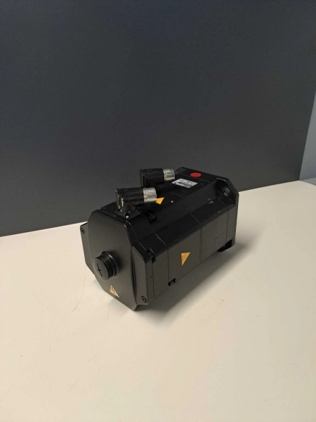
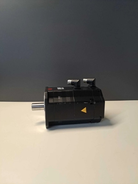
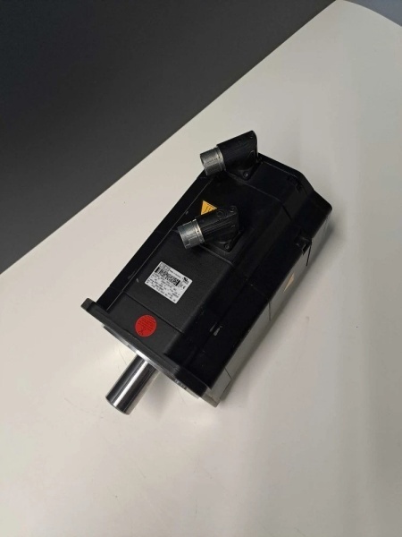
Description
Hard-Numbers: Technical Specifications
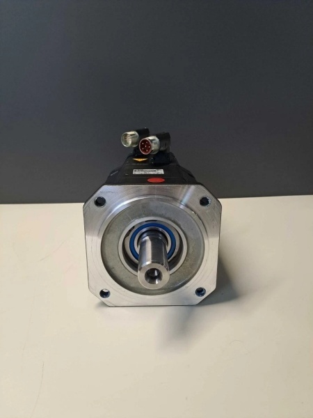
- Frame Size: 100 mm shaft height
- Continuous Torque (M0) : 27.0 Nm (239 in-lb)
- Rated Torque (MN) : 15.5 Nm (137 in-lb)
- Rated Speed (nN) : 2000 RPM
- Continuous Power: 4.29 kW (5.8 HP)
- Rated Current (IN) : 11.8 A
- Stall Current (I0) : 19.0 A
- Voltage Constant: 90 V/kRPM
- Torque Constant: 1.42 Nm/A
- Resistance: 0.55 ohms (line-to-line)
- Inductance: 4.2 mH (line-to-line)
- Feedback: Multi-pole Resolver (Resolver P=4) with Drive-CLiQ interface
- Cooling: Natural convection
- Thermal Time Constant: 35 min
- Inertia: 12.0 kg·cm²
- Weight: 21 kg (46 lb)
- Holding Brake: None (plain shaft variant)
- IP Rating: IP65 (standard)
- Mounting: IEC flange 100 mm with plain shaft (tolerance N)

1FK7101-5AY81-1SH3-Z
The Real-World Problem It Solves
You need 27 Nm torque in a 100 mm frame, but the environment is electrically noisy enough to make optical encoders unreliable. Resolver feedback shrugs off oil mist, metal dust, and electrical interference, while Drive-CLiQ provides digital communication with the SINAMICS drive system.
Where you’ll typically find it:
- KUKA robot joint drives (especially wrist and elbow axes)
- High-speed machining center axis drives
- Automated welding and cutting applications
The bottom line: It delivers 27 Nm of continuous torque in a compact package, with resolver-based feedback that survives harsh industrial environments where optical encoders would fail catastrophically.
Hardware Architecture & Under-the-Hood Logic
This is an 8-pole brushless synchronous motor with rare-earth permanent magnets on the rotor. The stator windings generate a rotating magnetic field that synchronizes with the rotor magnets. A multi-pole resolver mounted on the non-drive end provides absolute position feedback through inductive coupling rather than optical sensing.
Signal flow breaks down like this:
- Drive outputs three-phase AC current to stator windings (U, V, W)
- Resolver excitation signal (typically 5-10 kHz) applied to rotor winding
- Resolver feedback signals (sine, cosine) return to drive for commutation
- Drive-CLiQ interface transmits resolver data digitally to SINAMICS controller
- Current vector aligns with rotor position via resolver-based commutation
- Magnetic interaction between stator field and rotor magnets produces torque
- KTY84 thermal switch monitors stator winding temperature (155°C trip point)
- Power connector rotates 270° for flexible cable routing
Field Service Pitfalls: What Rookies Get Wrong
Resolver Wiring ErrorsThe resolver has six wires: two excitation, two sine, two cosine. Techs cross them during motor replacement, causing position drift or complete commutation failure.
- Field Rule: Use the resolver cable diagram from the motor nameplate. Excitation pair typically has higher resistance (20-30Ω). Verify with a multimeter before connecting—incorrect wiring causes erratic motion and can damage the resolver interface card in the drive.
Resolver Zero Offset CalibrationWhen replacing this motor, the resolver zero position rarely matches the old motor exactly. Techs swap and run without recalibrating, then the robot joint drifts 5-10 degrees or crashes during coordinated motion.
- Quick Fix: Perform resolver zero calibration after installation. Most SINAMICS drives have a calibration routine (parameter P-0-xxxx). Follow the drive manual’s procedure to reference the mechanical zero position. Document the offset value—each motor has its own unique offset.
Drive-CLiQ Cable Confusion with ResolverTechs assume Drive-CLiQ handles resolver analog signals directly. The Drive-CLiQ connection is digital only—the resolver signals route through a separate analog cable or through a resolver-to-Drive-CLiQ adapter module.
- Field Rule: Check your configuration. If the resolver connects directly to the drive’s analog resolver input, you need a dedicated resolver cable (not Drive-CLiQ). If using a resolver-to-Drive-CLiQ adapter, the resolver cable plugs into the adapter, and Drive-CLiQ goes from adapter to drive. Don’t mix them up.
Ignoring Natural Cooling LimitsThis motor relies on natural convection—no fan, no liquid cooling. Techs mount it in sealed cabinets or block airflow, then wonder why it trips thermal protection during 3-hour cycles.
- Field Rule: Calculate RMS torque from your motion profile. If you’re above 75% of rated torque for extended periods (more than 30 minutes), add external cooling. Measure cabinet temperature rise—if internal ambient hits 45°C+, you need forced ventilation. A 120mm fan pulling air across the motor surface saves thousands in motor replacements.
S07 Variant SpecificsThe S07 suffix indicates a specific mechanical configuration (likely shaft geometry or mounting pattern). Techs treat it like a generic 1FK7101 and discover mounting holes don’t align or shaft keys don’t fit.
- Quick Fix: Verify the S07 mechanical specs against your application before ordering a replacement. Suffix codes modify flange pattern, shaft length, or keyway dimensions. Never assume mechanical interchangeability across suffix variants—measure before you buy.


