
Description
Hard-Numbers: Technical Specifications
- Pressure Range: 0-100 psig (0-6.9 bar)
- Output Signal: 4-20 mA (2-wire loop-powered)
- Communication: HART Protocol (digital superimposed on 4-20 mA)
- Accuracy: ±0.1% of calibrated span
- Long-Term Stability: ±0.1% per year
- Supply Voltage: 10-35 VDC
- Load Resistance: 0-750 Ω @ 24 VDC
- Process Connection: 1/2″ NPT female
- Wetted Material: 316 Stainless Steel diaphragm
- Electrical Connection: 1/2″ NPT conduit entry
- Operating Temperature: -40°C to 85°C (-40°F to 185°F)
- Compensated Temperature: -10°C to 80°C (14°F to 176°F)
- Enclosure Rating: NEMA 4X (IP66) polycarbonate housing
- Response Time: <100 ms
- Safety Certification: SIL 2 capable, CSA, CE, ATEX
- Shock/Vibration: 50G, 20-2000 Hz
- Weight: 1.5 lbs (0.7 kg)

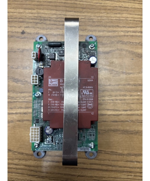
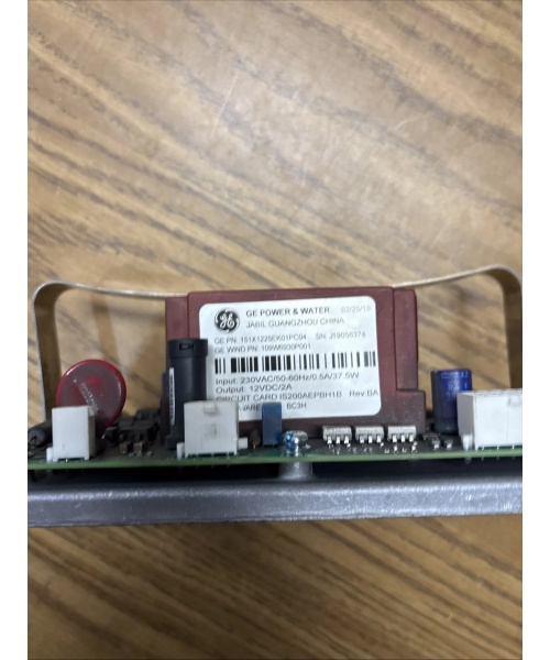
GE 151X1225EK01PC04
The Real-World Problem It Solves
Gauge-accuracy pressure measurement at the control room without local indicators. The 151X1230BR01SA04 provides continuous 4-20mA pressure feedback with HART diagnostics, enabling remote configuration and predictive maintenance.
Where you’ll typically find it:
- Pump discharge pressure monitoring
- Compressor suction and discharge lines
- Pressure control loop feedback for control valves
Bottom line: Continuous analog pressure transmission with smart diagnostics for field device management.
Hardware Architecture & Under-the-Hood Logic
This transducer uses a piezoresistive sensor element bonded to a 316SS diaphragm. Process pressure deflects the diaphragm, causing strain on the piezoresistive elements. A Wheatstone bridge circuit converts strain to millivolt-level electrical signal. An internal ASIC amplifies and conditions the signal, outputting a 4-20 mA current proportional to pressure. HART modem superimposes digital communication on the analog loop for configuration and diagnostics. Non-volatile memory stores calibration, configuration, and diagnostic data.
Signal flow:
- Process pressure applied to 316SS diaphragm
- Diaphragm deflection creates strain on piezoresistive sensor
- Wheatstone bridge converts strain to mV signal
- Signal conditioning ASIC amplifies and compensates for temperature
- Current loop driver outputs 4-20 mA proportional to pressure
- HART modem adds FSK digital signal to analog loop
- Output terminals deliver 4-20 mA + HART to control system
- ASIC continuously monitors sensor health and stores diagnostics
GE 151X1225EK01PC04
Field Service Pitfalls: What Rookies Get Wrong
Ground loops and common mode voltageMultiple ground references create current loops that corrupt the 4-20 mA signal. I’ve seen technicians ground the shield at both ends, causing drift of 1-2 mA.
- Field Rule: Ground the shield at the DCS/PLC cabinet only. Never ground both ends. Use an isolated power supply if the transducer is grounded to the process. Measure ground potential between field device and control room—should be less than 1 VAC. If ground loops persist, install a signal isolator between transducer and control system.
Incorrect pressure range causes loss of resolutionSelecting a range larger than needed reduces usable resolution. I’ve seen 0-1000 psig transducers on 0-100 psig applications, resulting in 10% loss of accuracy and resolution.
- Field Rule: Match the transducer range to your normal operating pressure. For a 0-100 psig application, use a 0-100 or 0-150 psig transducer—avoid 0-500 psig or larger. Re-range the transducer via HART communicator during commissioning if needed. Document the calibrated range and accuracy in your calibration records.
Leakage currents from VFD outputsVariable frequency drives inject high-frequency noise onto power lines. I’ve seen 4-20 mA signals corrupted by leakage currents from VFD-powered loops, causing erratic readings.
- Field Rule: Use separate power supplies for instrument loops and VFDs. Route instrument power cables away from VFD output cables. Use twisted shielded pair for the 4-20 mA signal with proper termination. Consider installing a signal conditioner with low-pass filtering if noise persists.
Improper grounding of HART communicatorHandheld HART communicators require proper grounding. I’ve seen technicians float the communicator, causing communication failures and potentially damaging the device.
- Field Rule: Connect the HART communicator ground terminal to the same earth ground as the control system. Never float the communicator. Use a ground strap or earth ground connection. Test HART communication by reading a known parameter (e.g., PV, URV, LRV). If communication fails, verify all connections and ground continuity.
Forgotten vent calibration for gauge pressureGauge pressure transducers reference atmospheric pressure. I’ve seen technicians forget to expose the vent, causing the transducer to read zero at atmospheric pressure as if it were absolute pressure.
- Field Rule: Verify the vent path is unobstructed during installation. For gauge pressure transducers, ensure the vent port is not plugged or sealed. Perform a zero calibration at atmospheric pressure. For absolute pressure applications, verify the transducer is an absolute pressure variant and calibrate accordingly. Document the reference pressure (gauge vs absolute) in your configuration records.
Over-tightening process connections damages the diaphragmThe 1/2″ NPT threads can over-compress the diaphragm. I’ve seen technicians over-tighten with pipe wrenches, causing the diaphragm to warp and shift calibration.
- Field Rule: Use thread sealant (PTFE tape or pipe dope) and torque to 15-20 ft-lbs maximum. Never use a cheater bar. Install a pressure snubber or needle valve for high-pressure pulsating applications. If leakage occurs, do not over-tighten—check thread alignment and sealant. Never apply excessive lateral force to the process connection.
Ignoring HART diagnosticsThe transducer provides rich diagnostic data. I’ve seen technicians ignore alarms and warnings, leading to unexpected failures and downtime.
- Field Rule: Read HART diagnostics weekly or monthly via AMS or handheld communicator. Monitor sensor status, temperature, and electronics health. Look for warnings like “sensor drift” or “temperature out of range.” Create a trend log of key parameters (e.g., PV, sensor temperature) and review trends for anomalies. Replace transducers at end-of-life or when diagnostics indicate degradation.
Commercial Availability & Pricing Note
Please note: The listed price is for reference only and is not binding. Final pricing and terms are subject to negotiation based on current market conditions and availability.


