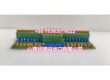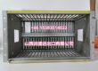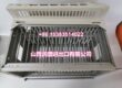
Product Core Brief
- Model: IS410SRLYS2A (board) / IS400SRLYS2ABB (assembly)
- Brand: General Electric (GE)
- Series: Mark V (Speedtronic)
- Core Function: RST relay I/O board that routes trip signals, relay driver outputs, and generator/line signals for gas turbine control systems.
- Product Type: RST Relay I/O Board
- Key Specs: JD trip signal output | JE generator/line signal routing | Relay driver outputs | 3PL data bus to STCA board | 2PL power distribution from TCPS
- Condition: New Original / New Surplus
Product Introduction
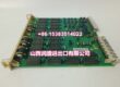
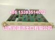
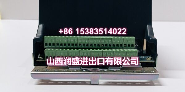
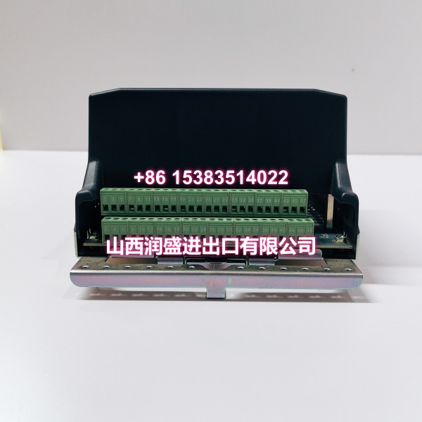
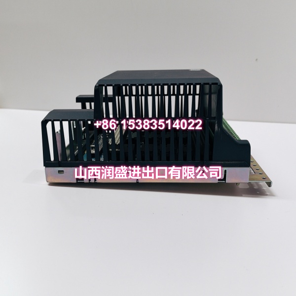
The GE IS410SRLYS2A (board-level designation) / IS400SRLYS2ABB (assembly-level designation) is a relay I/O board in GE’s Mark V Speedtronic turbine control system. It handles relay driver outputs, trip signal routing, and generator/line signal exchange — all critical for turbine protection logic and process regulation.
This board interfaces with the Mark V I/O core through multiple connectors: the 2PL connector distributes power from the TCPS board to the core; the 3PL connector routes conditioned signals to the STCA board via the COREBUS data link; the JD connector sends trip signals from the core to the TCTG board; and the JE connector handles pulse signals, generator/line signals, relay driver outputs, and servo valve driver outputs to/from the TCQC board.
Like the TCQA analog I/O board, the relay I/O board is mounted in the I/O core (R1, R2, R3) and works in tandem with terminal boards to scale, condition, and route discrete and relay signals for the Mark V controller’s trip logic and process control algorithms.
Key Technical Specifications
| Parameter | Value |
|---|---|
| Manufacturer | General Electric (GE) |
| Product Type | RST Relay I/O Board |
| Series | Mark V (Speedtronic) |
| Supported Signals | Relay driver outputs, trip signals, generator/line signals, pulse signals, servo valve driver outputs |
| Power Connector | 2PL (power distribution from TCPS board) |
| Data Bus Connector | 3PL (to STCA board via COREBUS) |
| Trip Signal Connector | JD (to TCTG board) |
| Generator/Line Signal Connector | JE (to TCQC board) |
| Application | Gas turbine control, trip logic, process regulation |
| Origin | USA |
Quality Control Process
Every IS410SRLYS2A / IS400SRLYS2ABB goes through a full functional bench test before it ships. We start with a visual PCB inspection — checking for cold solder joints, swollen capacitors, and corrosion on all connector headers (2PL, 3PL, JD, JE). Relay boards in turbine control rooms see frequent switching cycles, and contact wear or solder fatigue can cause intermittent trip signal failures.
Then we power it up on a regulated DC supply and verify the 2PL power rail voltages are within spec. We inject discrete signals through the JE connector and verify the relay driver outputs toggle correctly. We test the JD trip signal path by simulating a trip condition and confirming the signal routes properly to the TCTG board interface. We also verify the 3PL data bus communication with the STCA board by confirming the board responds with its hardware ID packet. Finally, we check all relay driver output channels for correct switching behavior and contact resistance. Each unit ships in anti-static foam with a moisture barrier bag.
Replacement Pitfall Guide
❗ Know which part number you’re ordering. IS410SRLYS2A is the board-level designation; IS400SRLYS2ABB is the assembly-level designation. They refer to the same functional unit, but your procurement system or OEM documentation may list one or the other. Confirm which format your BOM uses to avoid confusion during ordering.
❗ Verify the JD trip signal pinout. The JD connector carries trip signals from the core to the TCTG board — this is safety-critical wiring. If you’re cross-wiring from a different relay board revision, a pinout change can bypass trip logic entirely. Always compare the wiring diagram on your existing board’s label against the replacement before connecting.
❗ Check the 3PL data bus communication. The 3PL connector routes signals to the STCA board via the COREBUS data link. If the replacement board doesn’t respond with its hardware ID packet after installation, the Mark V controller won’t recognize it and the I/O core will fault. Verify communication before closing the panel.
❗ Confirm backplane power headroom. The 2PL connector distributes power from the TCPS board to the entire I/O core. If you’re adding a new relay board without verifying remaining headroom, you can cause brownouts on adjacent modules — especially if the relay driver outputs are driving multiple loads simultaneously.
❗ Don’t skip the trip logic verification. After installing a replacement relay board, simulate a trip condition and verify the JD connector routes the signal correctly to the TCTG board. A relay board that passes bench tests but has a misrouted trip signal is worse than a failed board — it gives you a false sense of security until you actually need it.
Keep these in mind and you’ll cut 90% of rework time.
Compatibility Matrix & Benchmarks
| Original Model | Replacement / Successor Model | Compatibility Level | Migration Notes |
|---|---|---|---|
| IS410SRLYS1A | Direct | Earlier revision; verify firmware and pinout match | |
| IS410SRLYS2B | Direct | Suffix “2B” variant; verify firmware revision match | |
| Mark V legacy relay I/O | Direct | Drop-in for Mark V RST cores | |
| IS420YARCS1B | Needs Adaptation | Mark VIeS variant; requires full I/O map migration |
- Trip Signal Routing: JD connector to TCTG board for turbine protection logic
- Data Bus Communication: 3PL connector to STCA board via COREBUS with hardware ID packet response