Product Core Brief
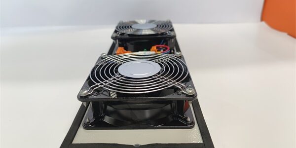
- Model: FC-FANWR-24R
- Brand: Honeywell Safety Solutions
- Series: FSC / Safety Manager SIL SIS Chassis Auxiliary Hardware
- Core Function: Dual redundant 24VDC cooling fan module with built-in airflow fault detection to maintain safe operating temperature for SIL logic solver and safety IOM cards
- Product Type: Hot-Swap Redundant Rack Cooling Fan Assembly
- Key Specs: Dual 24VDC brushless fans | Independent fault sensing per fan | Hot-swap chassis slot mount | Over-temperature alarm outputNote: Discontinued end-of-life SIS rack accessory hardware, stocked only as unopened New Surplus inventory.
Key Technical Specifications
- Compatible Chassis: All standard FSC Safety Manager main and expansion rack enclosures
- Fan Configuration: Two independent brushless DC fans, 1+1 redundant airflow layout
- Operating Input Voltage: 20–32VDC nominal 24VDC rack auxiliary power
- Single Fan Current Draw: 0.22A @ 24VDC; total max assembly draw 0.44A
- Airflow Rating: 14 CFM per fan; full rack cooling capacity 28 CFM dual-fan operation
- Fault Detection Logic: Hall-effect speed monitoring; triggers rack minor fault alarm if any fan speed drops below 70% nominal RPM
- Mechanical Lifespan: 70,000 hours MTBF at 40°C continuous cabinet ambient
- Mount Style: Standard dedicated rack fan slot, slide-in hot-swap design with integrated lock latches
- Signal Output: Isolated dry contact fault relay for remote cabinet temperature monitoring systems
- Ambient Operating Range: -40°C to +70°C cabinet surrounding air
- Hazardous Location Rating: FM Class I Div 2 Groups A/B/C/D cabinet mounting certified
- Environmental Protection: Conformal coated fan control PCB for corrosive refinery/offshore environments
- Physical Dimensions: 182mm H × 48mm W × 110mm D; net weight 0.29kg
Product Introduction
This dual-fan assembly provides redundant forced convection cooling for heat-generating SIS logic solver and analog/digital safety IOM hardware. Separate speed sensing circuits flag stalled or degraded fan operation to the Safety Manager, preventing over-temperature shutdown of critical SIL safety loops.Hot-swap slide-in construction allows single fan replacement without full rack power isolation, cutting maintenance downtime for continuous process safety systems.
QA & Testing SOP (Transparency Building)
- Incoming Inspection: Match serial numbers to OEM batch logs; inspect fan impellers for deformation, PCB coating delamination, and broken fault signal terminal pins; confirm factory anti-static packaging seal integrity.
- Live Testing: Install into a bench Safety Manager rack powered by a Fluke 115 24VDC supply; run 24-hour continuous dual-fan runtime testing with simulated single fan stall fault injection to validate alarm trip logic.
- Electrical Testing: Megger insulation test >10MΩ between 24VDC power terminals and fault relay signal wiring; verify dry contact relay closes reliably when fan RPM falls below detection threshold.
- Firmware/Config Backup: No onboard programmable firmware; photograph factory default fault signal jumper positions for field service reference.
- Final QC & Packaging: Attach serialized printed test pass tag; seal unit in foam-lined static-shielded bag to protect fan motor control PCB during transit and storage.
Installation Pitfalls & Guide (Engineer to Engineer)
❗ Firmware Rev Compatibility Risk: Safety Manager R150 and older solver firmware does not log fan speed degradation history; upgrade rack logic solver firmware to R160 or newer before fan swap to avoid unrecorded over-temperature risk on SIL racks.❗ Jumper Configuration Loss: Capture photos of fault relay NO/NC jumpers on the old unit; misconfigured jumpers reverse alarm logic and fail site cabinet monitoring trip tests.❗ Mounting Airflow Mismatch: This assembly’s air intake/exhaust orientation is fixed for standard FSC rack airflow routing; reversed mounting traps hot air inside the chassis and accelerates IOM thermal degradation.❗ Power Draw Miscalculation: Adding multiple fan modules to a single rack auxiliary 24VDC bus can overload rack power supplies; calculate total auxiliary load to maintain minimum 20% supply current headroom.❗ ESD Component Damage Risk: Ungrounded technicians can damage fan speed sensor ICs during hot-swap swaps; latent damage creates intermittent false fan fault alarms that surface after weeks of runtime.
4-step replacement guide:
- Pre-install: Locate rack auxiliary 24VDC power disconnect; attach grounded anti-static wrist strap to chassis DIN rail ground lug.
- Removal: Document fault relay jumper positions via photo; release side lock latches, slide the assembly partially out, disconnect 24VDC power and fault signal wiring, fully extract the unit from the fan slot.
- Install: Slide new hardware into the dedicated rack fan slot, replicate all fault signal jumper settings from reference photos, reconnect 24VDC power and fault alarm wiring, engage both side lock latches fully.
- Power-on Test: Restore rack auxiliary power; open Safety Builder diagnostic screens to confirm both fans report normal RPM with no active airflow fault flags.
FAQ (Frequently Asked Questions)
Q: Can this fan assembly maintain adequate cooling if one fan stalls during runtime?A: Yes. A single operational fan delivers 14 CFM of cooling airflow, sufficient to hold chassis internal temperature within OEM design limits for short-term maintenance windows. Long-term single-fan operation triggers persistent minor rack fault alarms per IEC 61508 site safety rules.Q: Does the hardware support true hot-swapping without full rack power shutdown?A: The fan module can be removed while the main SIS logic solver and IOM backplane remain energized, but auxiliary 24VDC fan supply must be disconnected before detaching wiring to avoid transient voltage spikes on the fault signal circuit.Q: What warranty coverage applies to bench-tested surplus inventory units?A: All stocked units carry a 12-month functional warranty covering fan motors, speed sensor circuits, and fault relay PCB defects. Damage from reversed airflow mounting, overloaded auxiliary power buses, or ungrounded ESD handling is excluded from coverage.Q: Is there a direct drop-in modern replacement for this discontinued fan hardware?A: Current-generation Safety Manager rack fan modules offer redundant cooling and fault monitoring, but rack slot mechanical tolerances and fault relay contact pinouts differ; minor chassis wiring retermination and fault alarm logic revalidation is required with no unmodified direct swap path.Q: What over-temperature hazard control does the fan fault signal provide?A: The isolated dry contact relay hardwires to site DCS or cabinet monitoring systems, triggering operator alerts before chassis heat buildup forces an automatic SIS rack shutdown, a mandatory fault coverage requirement for SIL2/SIL3 continuous production safety racks.Q: Can multiple FC- assemblies be wired in parallel to a single auxiliary 24VDC power feed?A: Physically permitted, but each rack power supply has fixed auxiliary current limits. Calculate combined fan load and add separate auxiliary power distribution fuses for each fan module to prevent cascaded power loss if one fan motor shorts.Q: Can this cooling unit be used inside Experion C300 Series-C DCS racks?A: No. The form factor, slot locking mechanism, and airflow routing geometry are exclusive to FSC Safety Manager SIS chassis. C300 racks use separate non-compatible fan accessory hardware with different backplane power signal pinouts.