Product Core Brief
- Model: DS200DCFBG2BNC
- Brand: GE Energy / GE Industrial Systems
- Series: GE Mark VI Speedtronic / DS200 Series
- Core Function: DC feedback power supply board for GE Mark VI turbine control systems, providing control-level DC power, enclosure fan power, and AC/DC monitoring.
- Product Type: Mark VI DC Feedback / Power Supply Board
- Condition: New Original / New Surplus (subject to available stock)
Key Technical Specifications
- Part Number:
- Platform: GE Mark VI Speedtronic Turbine Control System
- Board Type: DC Feedback Power Supply Board (DCFB function code)
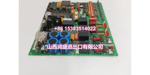
- Connectors: 18 plug connectors and 9 mating connectors for I/O signal routing
- Mating Connector Labels: V1–V3, P1A, P2A, VM1A, VM1B, VB2A, VM2BA (located at upper-left)
- Configuration: 7 DIP switches, 12 configurable jumpers
- Test Points: 5 onboard TP test points for voltage monitoring
- Protection: 3 onboard fuses with status indicators (2 LEDs + 1 neon lamp)
- DIP Switch Function: Selects AC line voltage and voltage applied to DC bridge voltage feedback VCO circuit and DC motor voltage feedback circuit
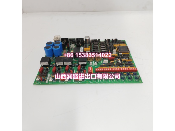
- Internal Components: 7 transformers, oscillator chip, 1 relay, heatsink, 50+ resistor network arrays, ICs, capacitors, and resistors (CCR + metal film)
- Typical Application: Gas/steam turbine control, Mark VI drive/exciter power supply
Product Introduction (No Fluff)
The DS200DCFBG2BNC is a DC feedback power supply board for the GE Mark VI Speedtronic turbine control system. It provides control-level DC power to the drive system, supplies power to enclosure cooling fans, and includes AC/DC monitoring circuits for feedback on electrical parameters.
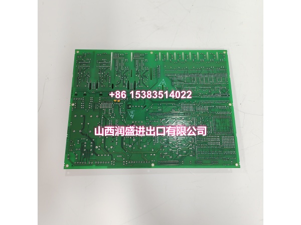
The board interfaces with the system through 18 plug connectors and 9 mating connectors, with mating connectors labeled V1–V3, P1A, P2A, VM1A, VM1B, VB2A, and VM2BA located at the upper-left corner of the PCB. User configuration is handled through 7 DIP switches and 12 jumpers. The DIP switches select the AC line voltage and the voltage applied to the DC bridge voltage feedback VCO circuit and DC motor voltage feedback circuit.
Onboard protection includes 3 fuses, with 2 LED indicators and 1 neon lamp to signal blown fuses. Five test points allow technicians to monitor voltage levels during commissioning or troubleshooting. The board contains 7 transformers, an oscillator chip, a relay, a heatsink, 50+ resistor network arrays, and various ICs, capacitors, and resistors using both carbon composite and metal film materials.
The Mark VI platform is GE’s successor to the Mark V turbine control system, offering improved performance and integration for gas and steam turbine applications. DS200DCFBG2BNC is typically available as surplus or refurbished stock for legacy installations.
QA & Testing SOP (Dynamic & Transparent)
Each surplus unit undergoes:
- Part Number Verification: Confirm the label reads DS200DCFBG2BNC. Check for GE markings and board revision.
- Visual Inspection: Inspect the PCB surface, all 18 plug connectors, 9 mating connectors, DIP switches, jumpers, fuses, LEDs, and neon lamp for corrosion, burns, or physical damage.
- Connector Check: Verify all plug and mating connectors (V1–V3, P1A, P2A, VM1A, VM1B, VB2A, VM2BA) are intact with no bent pins or damaged contacts.
- Fuse Check: Verify all 3 onboard fuses are present and intact. Replace if blown or corroded.
- Indicator Check: Confirm 2 LED indicators and 1 neon lamp are present and not damaged.
- DIP Switch & Jumper Check: Document all 7 DIP switch and 12 jumper positions. Verify they are intact.
- Test Point Check: Confirm all 5 TP test points are accessible and not corroded.
- Component Inspection: Verify transformers, relay, heatsink, and resistor arrays show no signs of thermal damage or leakage.
- Continuity Check: Where possible, verify continuity across key power rails, fuse holders, and connector pins.
- Packaging: Pack in anti-static bags with foam cushioning. Protect all connectors, fuses, and DIP switches during transit.
Installation Pitfalls & Guide (Engineer to Engineer)
Match DIP switch and jumper settings exactly. Before removing the old board, document all 7 DIP switch positions and 12 jumper settings. The replacement must match the original configuration precisely.
Verify connector orientation. With 18 plug connectors and 9 mating connectors, take care to match each connector to its correct position. Reference the original board or system documentation.
Check fuse condition before power-up. Blown fuses may indicate an upstream fault. Replace fuses only after verifying the cause of the failure.
Use proper ESD protection. Always wear a grounded wrist strap when handling Mark VI boards.
Monitor voltage at test points. After installation, use the 5 onboard TP test points to verify correct DC output levels before full system commissioning.
Confirm DIP switch voltage selection. The DIP switches set the AC line voltage and DC feedback circuit voltage. Incorrect settings can cause improper operation or damage.
Document board location. Record the rack, slot, and all connector assignments for future reference.
Installation Steps:
- Pre-install: Confirm part number DS200DCFBG2BNC. Document all DIP switch, jumper, and connector positions on the existing board.
- Power Down: Follow proper turbine control system shutdown procedures. Verify no hazardous voltage is present.
- Remove Old Board: Disconnect all 18 plug connectors and 9 mating connectors. Remove the board from the rack.
- Configure New Board: Set all 7 DIP switches and 12 jumpers on the replacement to match the original.
- Install Board: Seat the board in the correct location. Reconnect all connectors securely, verifying orientation.
- Commission: Power up the system. Verify LED/neon indicators. Check voltage levels at test points. Confirm normal turbine control operation.
Technical FAQ
1. What is the DS200DCFBG2BNC? It is a DC feedback power supply board for the GE Mark VI Speedtronic turbine control system, providing control-level DC power, enclosure fan power, and AC/DC monitoring.
2. What system is it used in? It is used in GE Mark VI turbine control systems for gas and steam turbine applications.
3. How many connectors does it have? It has 18 plug connectors and 9 mating connectors for I/O signal routing.
4. Does it require configuration? Yes. The board has 7 DIP switches and 12 configurable jumpers that must be set according to the system requirements.
5. How do I know if a fuse is blown? The board has 2 LED indicators and 1 neon lamp that signal blown fuses on the power rails.
6. What do the DIP switches control? The DIP switches select the AC line voltage and the voltage applied to the DC bridge voltage feedback VCO circuit and DC motor voltage feedback circuit.
7. Is this product still in production? The Mark VI platform has been superseded by Mark VIe. DS200DCFBG2BNC is typically available as surplus or refurbished stock.
8. What warranty do you offer on surplus stock? Terms vary by condition and availability. For surplus industrial modules, we typically provide a short functional guarantee. Confirm details at time of order.