Product Core Brief
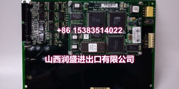
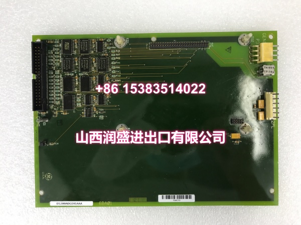
- Model: DS200ADGIH1AAA
- Brand: GE / General Electric
- Series: Speedtronic Mark V DS200
- Core Function: Auxiliary interface board for GE Speedtronic Mark V turbine and drive control systems, providing additional connection, jumper configuration, and test-point access inside the drive cabinet.
- Product Type: Auxiliary Interface PCB
- Key Specs: 1 × 40-pin connector, 1 × 6-pin connector, 60 jumpers, multiple test points, screw-mounted, approx. 8″ × 6″
- Condition: New Original / New Surplus
Key Technical Specifications
- Part Number:
- Product Family: GE Speedtronic Mark V DS200 Series
- Function: Auxiliary interface board for Mark V turbine/drive control systems
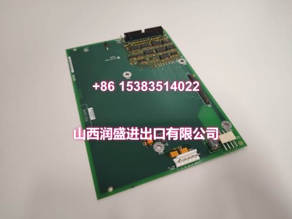
- Connectors: 1 × 40-pin connector, 1 × 6-pin connector
- Jumpers: 60 jumpers for configuration
- Test Points: Multiple onboard test points
- Mounting: 4-hole screw mount, aligned to board rack position
- Board Size: Approximately 8 in wide × 6 in long
- Installation Location: Drive cabinet / inverter board cabinet
- Typical Applications: GE Mark V gas/steam turbine control, drive cabinet I/O expansion, auxiliary signal interface, legacy Mark V system maintenance
Product Introduction (No Fluff)
The GE DS200ADGIH1AAA is an auxiliary interface board for the GE Speedtronic Mark V turbine and drive control platform. It is designed to be installed in the drive cabinet and provides additional interface capability through a 40-pin connector, a 6-pin connector, 60 jumpers, and multiple test points.
This board is typically used to support auxiliary signal routing, configuration, and test access within Mark V control systems. It is commonly found in gas turbine, steam turbine, and industrial drive applications where legacy Mark V DS200 hardware is installed. Because the Mark V platform is now legacy, DS200ADGIH1AAA is mainly used for spare replacement, maintenance, and migration support.
Note: Detailed electrical ratings, signal assignments, and jumper maps should be confirmed from the actual board label, wiring drawings, and GE Mark V documentation before installation.
QA & Testing SOP (Dynamic & Transparent)
For a legacy Mark V auxiliary interface board, we verify identification, physical condition, connector integrity, and configuration readiness before release.
- Part number verification: Confirm DS200ADGIH1AAA on the board label. Record revision, serial number, and date code where available.
- Visual inspection: Check the PCB, connectors, jumpers, test points, mounting holes, and conformal coating for corrosion, burn marks, or mechanical damage.
- Connector inspection: Verify the 40-pin and 6-pin connectors for bent pins, contamination, or poor contact.
- Jumper configuration check: Record the existing 60-jumper configuration against the reference drawing; do not change jumpers without verified documentation.
- Test-point inspection: Confirm test points are intact and accessible; functional testing requires qualified personnel and calibrated test equipment.
- Cabinet compatibility check: Confirm the board matches the target Mark V drive cabinet slot and wiring layout.
- Functional test limitation: Full functional testing requires a compatible Mark V cabinet and control environment; if not available, testing is limited to visual, electrical, and connector checks.
- ESD-safe packaging: Ship in anti-static bags with foam protection. Include part number, revision, and inspection status on the label.
Installation Pitfalls & Guide (Engineer to Engineer)
❗ Confirm it is the correct Mark V board revision. DS200ADGIH1AAA may have related variants; always match the full part number before replacement.
❗ Do not change jumpers without documentation. The board uses 60 jumpers; incorrect settings can affect signal routing or system behavior.
❗ Handle as an ESD-sensitive board. Use an anti-static wrist strap and anti-static packaging during removal, inspection, and installation.
❗ Verify connector orientation. The 40-pin and 6-pin connectors must be reconnected to the same positions as the original board.
❗ Only qualified personnel should perform live testing. Test points are provided for service use; testing requires calibrated equipment and proper safety procedures.
❗ This is a legacy Mark V product. The Speedtronic Mark V platform is no longer current; use this board mainly for maintenance, spare replacement, or migration projects.
Replacement steps:
- Pre-install: Record slot location, cable labels, jumper settings, and connected subsystems.
- Isolate: Follow plant and turbine control safety procedures before opening the drive cabinet.
- Remove: Disconnect cables, remove mounting screws, and withdraw the board without forcing connectors.
- Install: Seat the replacement DS200ADGIH1AAA, reinstall screws, and reconnect cables to the original positions.
- Commission: Verify connector seating, jumper configuration, test-point references, cabinet indicators, and system communication before returning to service.
Technical FAQ
What is the GE DS200ADGIH1AAA?
It is a GE Speedtronic Mark V auxiliary interface board used in turbine and drive control cabinets.
What connectors does it have?
It has one 40-pin connector and one 6-pin connector, plus 60 jumpers and multiple test points.
Where is it installed?
It is designed for installation in the drive cabinet or inverter board cabinet of a Mark V system.
Can it be used in Mark VI or Mark VIe systems?
No. It belongs to the Mark V DS200 series and is not directly compatible with newer Mark VI/VIe platforms.
Is this board still in production?
The Mark V platform is legacy and largely discontinued. Availability is typically through surplus or spare parts channels.