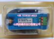
Product Core Brief
- Model: D20ME 526-2005-216943
- Brand: GE Energy / GE Intelligent Platforms
- Series: GE D20 / D200 RTU Family
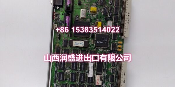
- Core Function: Main processor module for the GE D20/D200 substation controller, providing central CPU processing, protocol conversion, data concentration, and local automation logic.
- Product Type: VME Main Processor / CPU Module
- Condition: New Original / New Surplus (subject to available stock)
Key Technical Specifications
- Part Number: D20ME 526-2005-216943 (526-2005 series main processor board)
- Platform: GE D20 / D200 Remote Terminal Unit (RTU) / Substation Controller
- Processor: 32-bit main processor with digital signal processing capability
- Bus Interface: VMEbus, installs in D20/D200 CCU chassis
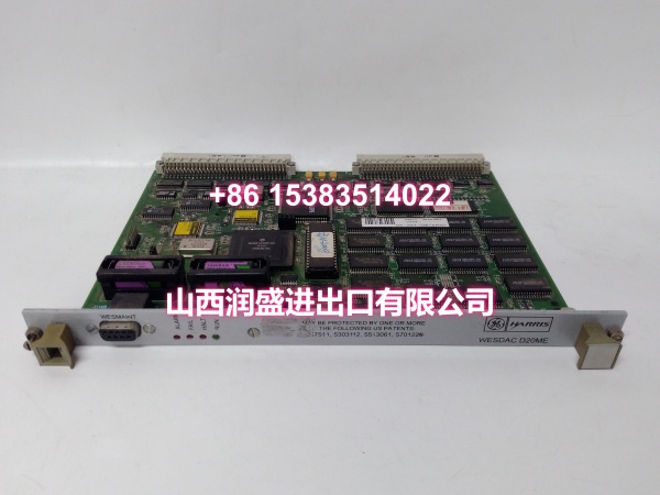
- Memory: Boot EPROM plus static RAM, non-volatile RAM, and flash memory; typical configurations include approximately 1.5 MB SRAM, 0.5 MB NVRAM, and 2 MB flash (varies by firmware revision)
- Battery Backup: Two 3.6 V lithium batteries for NVRAM retention during power loss
- Real-Time Clock: On-board RTC with internal clock source; non-boot nodes synchronize to node 1 in multi-node D200 systems
- Jumper Configuration: JP1 for VME master/slave role, JP2 for VME bus address, JP3 for RTC source, JP4 for watchdog timer; JP5/JP6/JP7 are factory-test only
- Watchdog Timer: Hardware watchdog configurable via JP4
- LED Indicators: BATT, POWER, ACCESS, D20 EM, ETHERN, MEMORY status LEDs
- Typical Application: Substation automation, SCADA data concentration, protocol conversion, distributed RTU control, and local PLC/PID logic
Product Introduction (No Fluff)
The D20ME 526-2005-216943 is a main processor module for the GE D20/D200 substation controller platform. It serves as the central CPU for the RTU, handling data concentration from I/O modules, protocol conversion for SCADA communication, and execution of local automation logic.
The D20/D200 platform is a field-proven substation controller used in tens of thousands of installations worldwide. The D20ME processor board installs in a VME-compatible D20 or D200 CCU chassis and acts as the system’s primary computational engine. Manufacturing of the D20/200ME substation controllers has been discontinued, with GE Vernova recommending the G500 or D20MX/D200MX as alternatives; however, D20 I/O options remain available for use with G500 products.
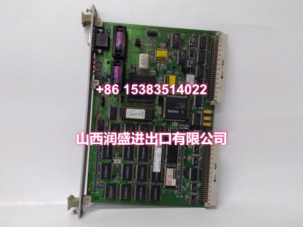
The 526-2005 series D20ME board features a 32-bit processor, on-board flash and NVRAM for configuration and application storage, and battery-backed memory retention. Jumper settings on the board determine the VME bus role (master/slave), board address, RTC source, and watchdog behavior. In multi-node D200 configurations, the boot node (address 1) uses its internal RTC, while non-boot nodes synchronize their clocks to node 1.
This module is commonly found in utility substations, power generation facilities, and industrial SCADA systems where reliable, real-time RTU processing is required.
QA & Testing SOP (Dynamic & Transparent)
Each surplus unit undergoes:
- Part Number Verification: Confirm the label reads D20ME 526-2005-216943. Check for GE markings and board revision.
- Visual Inspection: Inspect the VME connector edge, PCB surface, battery holders, jumper blocks, and LED indicators for corrosion, damage, or leakage.
- Battery Check: Verify the two 3.6 V lithium batteries are present and not leaking. For long-term storage, batteries should be disconnected.
- Jumper Verification: Confirm JP1–JP4 jumper settings match the intended system configuration (master/slave, address, RTC, watchdog).
- VME Connector Check: Verify all VME bus connector pins are intact, straight, and free of oxidation.
- Mechanical Fit Check: Verify the board seats correctly into a compatible D20/D200 VME chassis slot.
- Power-Up Test: Install in a known-good D20/D200 chassis. Verify POWER and ACCESS LEDs indicate normal operation.
- Boot Verification: Where possible, confirm the board boots and is recognized by the system via ConfigPro or WESMAINT.
- Memory Check: Verify that SRAM, NVRAM, and flash are recognized and accessible.
- Packaging: Pack in anti-static bags with foam cushioning. Protect the VME connector edge and battery holders during transit.
Installation Pitfalls & Guide (Engineer to Engineer)
Confirm chassis compatibility. The D20ME requires a VME-compatible D20 or D200 CCU chassis. It will not fit in non-VME D20 chassis.
Set jumpers before installation. JP1 (VME master/slave), JP2 (VME bus address), JP3 (RTC source), and JP4 (watchdog) must be configured correctly for the target system. The boot node should be address 1 with internal RTC; non-boot nodes must sync to node 1.
Do not mix incompatible processor boards. In systems with more than three processor boards, D20 M++ cards cannot be used with D20ME or D20 EME cards due to stability issues.
Check battery condition. Leaking batteries can damage the PCB. Replace batteries if corrosion is present. Disconnect batteries for long-term storage.
Back up configuration first. Before replacing a processor board, back up the existing RTU configuration using ConfigPro.
Document slot and address. Record the VME slot position and board address. This is critical for multi-node D200 systems.
Verify redundant configuration. In redundant D20/D200 setups, confirm both CCUs have matching processor boards and configurations.
Installation Steps:
- Pre-install: Confirm part number D20ME 526-2005-216943 and chassis compatibility. Back up the existing configuration.
- Set Jumpers: Configure JP1–JP4 according to the system requirements (master/slave, address, RTC, watchdog).
- Power Down: De-energize the D20/D200 chassis before installing or removing VME boards.
- Insert Board: Seat the D20ME into the correct VME slot. Verify full mechanical engagement.
- Commission: Power up the system. Verify LED status. Load or restore the RTU configuration via ConfigPro. Confirm communication and I/O operation.
Technical FAQ
1. What is the D20ME 526-2005-216943? It is a main processor module for the GE D20/D200 substation controller, providing the central CPU, memory, and real-time processing for the RTU.
2. Is it compatible with all D20 chassis? No. It requires a VME-compatible D20 or D200 CCU chassis. It will not work in non-VME D20 chassis.
3. What memory does it include? The D20ME typically includes boot EPROM, static RAM (~1.5 MB), non-volatile RAM (~0.5 MB), and flash memory (~2 MB), though exact capacities may vary by firmware revision.
4. Does it need jumper configuration? Yes. JP1 through JP4 must be set for VME role, board address, RTC source, and watchdog. JP5–JP7 are factory-test only and should not be changed.
5. What software is used to configure it? ConfigPro (also referenced as Config Pro) is used for RTU configuration and maintenance. WESMAINT may also be used for certain diagnostics.
6. Is this product still in production? No. GE Vernova has discontinued manufacturing of the D20/200ME substation controllers. The G500 and D20MX/D200MX are recommended alternatives.
7. Can it be used in redundant configurations? Yes. The D20/D200 platform supports redundant processor configurations in applicable CCU chassis.
8. What warranty do you offer on surplus stock? Terms vary by condition and availability. For surplus industrial modules, we typically provide a short functional guarantee. Confirm details at time of order.