Product Core Brief
- Model: 369-HI-R-0-0-0-0-E
- Brand: GE Multilin
- Series: 369 Motor Management Relay
- Core Function: Protects and monitors three-phase AC motors with built-in RTD temperature monitoring, thermal overload modeling, ground fault protection, and Modbus RTU communication.
- Product Type: Motor Management / Motor Protection Relay
- Key Specs: HI control power 50–300 VDC / 60–265 VAC | 12 built-in RTD inputs | RS485 Modbus RTU | Enhanced diagnostics panel
- Condition: New Original / New Surplus
Key Technical Specifications
- Part Number: 369-HI-R-0-0-0-0-E
- Product Family: GE Multilin 369 Motor Management Relay
- Control Power: HI option, 50–300 VDC / 60–265 VAC, 50/60 Hz
- Motor Type: Three-phase AC induction motors
- Current Inputs: Phase current via 1 A or 5 A CTs
- Ground Fault Input: Core-balance / ground CT input supported
- RTD Inputs: 12 built-in RTD inputs (R option), typically Pt100 / Ni100 / Ni120 / Cu10 compatible
- Metering Option: None in this build; the metering position is “0”
- Communication: RS485 Modbus RTU standard; front-panel RS232 for configuration
- Analog Output: One standard analog output included with the base unit
- Diagnostics: Enhanced diagnostics and enhanced panel option (E)
- Configuration Software: EnerVista 369
Product Introduction (No Fluff)
The GE Multilin 369-HI-R-0-0-0-0-E is a three-phase motor management relay designed for MCC and switchgear applications where stator or bearing temperature monitoring is required. It combines current-based protection with 12 built-in RTD inputs, thermal overload modeling, ground fault supervision, and event recording.
This configuration is useful when the application needs direct temperature monitoring but does not require the optional metering package. Matching the exact option code prevents commissioning delays, especially during replacement of an existing relay in a live motor feeder.
QA & Testing SOP (Dynamic & Transparent)
For a motor protection relay with RTD inputs, we verify protection logic, temperature channels, and communication before release.
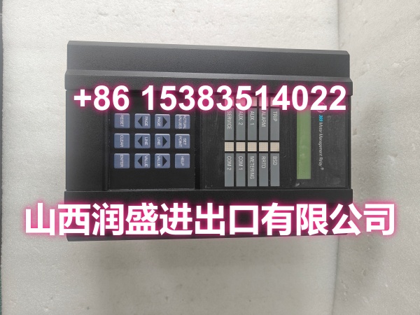
- Label and option verification: Confirm 369-HI-R-0-0-0-0-E on the nameplate. Check that the “R” RTD option is present and the metering position is “0.”
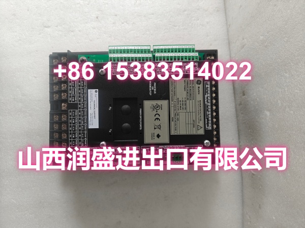
- Physical inspection: Inspect rear terminals, RTD connector block, front-panel keypad, display, and case latches. Reject units with cracked connectors, corrosion, or damaged display windows.
- Control power test: Apply rated HI control power and verify normal boot, display initialization, and LED status behavior.
- Secondary injection check: Use a relay test set to inject phase and ground current signals. Verify trip/alarm responses for overload, stall, unbalance, and ground fault functions according to configured setpoints.
- RTD channel validation: Simulate RTD resistance values to confirm temperature reading accuracy, alarm thresholds, and trip behavior for stator/bearing monitoring.
- Communication validation: Confirm RS485 Modbus RTU addressing and front-panel RS232 connectivity. Verify EnerVista 369 access if the port is enabled.
- ESD-safe handling: Pack in anti-static bags with foam support. Include part number, option code, and test status on the shipping label.
Installation Pitfalls & Guide (Engineer to Engineer)
❗ RTD wiring must be shielded. Unshielded RTD cables in motor MCCs can pick up noise and cause false temperature alarms. Use shielded twisted-pair cable and terminate the shield properly.
❗ This unit has no metering package. The fourth position is “0,” so voltage, power, and energy metering are not included. If your SCADA expects kW/kvar readings from this relay, they will not be available.
❗ Verify RTD type in software. The relay supports multiple RTD types, but the configured type must match the installed sensors. A Pt100 sensor configured as Cu10 will report incorrect temperatures.
❗ Do not assume communication settings carry over. Modbus address, baud rate, and parity must match the existing network. A relay may power up normally but still remain offline.
Replacement steps:
- Pre-install: Record existing setpoints, CT ratios, RTD assignments, Modbus settings, and I/O mappings. De-energize the control circuit safely.
- Removal: Label all CT, RTD, digital I/O, and communication wires. Remove the relay without stressing rear terminals.
- Install: Mount the new unit, verify CT polarity, RTD wiring, control power, and RS485 termination.
- Power-on test: Restore control power, load settings via EnerVista 369, verify RTD readings, and perform a controlled secondary injection test before returning the motor to service.
Technical FAQ
Is this a direct replacement for my existing 369 relay?
Yes, if your installed unit is also 369-HI-R-0-0-0-0-E. The “HI” supply, “R” RTD option, “0” metering position, and “E” enhanced diagnostics must all match. Swapping in a different option code can remove RTD inputs or change communication behavior.
Does this model include voltage and power metering?
No. In 369-HI-R-0-0-0-0-E, the metering position is “0.” If you need kW, kvar, kVA, PF, or energy metering, you would need an “M” option unit such as 369-HI-R-M-0-0-0-E.
How many RTD inputs does it support?
The “R” option provides up to 12 built-in RTD inputs for stator, bearing, ambient, or driven equipment temperature monitoring.
What communication does it support?
RS485 Modbus RTU is standard, with a front-panel RS232 port for local configuration. Ethernet, Profibus, DeviceNet, or fiber options depend on other submodels and are not indicated in this part number.
Do you offer warranty on surplus stock?
Warranty depends on lot condition and traceability. Functional testing can be provided, but exact warranty length should be confirmed before purchase.