
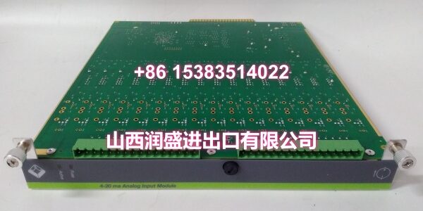
Product Core Brief
- Model: IOP310
- Brand: Metso
- Series: IOP300 Series I/O
- Core Function: Provides discrete digital input and output channels for DCS integration.
- Product Type: Digital Input/Output Module
- Key Specs: 24VDC Logic | 16 Channels | Galvanic Isolation
- Condition: New Original / New Surplus
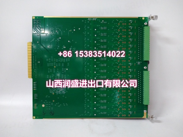
Key Technical Specifications
- Module Type: Digital Input/Output (DIO)
- Product ID:
- Signal Types: Dry Contact, 24VDC Sinking/Sourcing
- Channel Count: 16 Channels (Configurable I/O)
- Isolation: 500V Galvanic Isolation
- Update Rate: <10ms
- Operating Temp: -20°C to +70°C
- Backplane: IOP300 Series compatible
- Diagnostics: Short Circuit / Open Wire Detection
- Load Current: 0.5A per channel max
Product Introduction
Sitting in the IOP300 series rack, this card handles discrete control signals like limit switches, solenoids, and motor starters. It converts field-level 24VDC signals into clean logic for the CPU and drives outputs with built-in protection.
Field engineers rely on the per-channel isolation to prevent a shorted solenoid from taking out the entire module. The diagnostic LEDs make troubleshooting fast—you can see which channel is faulted without pulling out a multimeter.
QA & Testing SOP (Dynamic & Transparent)
Every Metso IOP310 gets a full digital workout, not just a power-on check. We start with a visual inspection under magnification, looking for cold solder joints or flux residue that screams “field repair.” Then we test all 16 channels by injecting 24VDC signals and verifying state changes in the status register.
Next, we test the output drivers by switching loads and measuring voltage drop across the FETs. We also simulate short circuits to confirm the protection circuitry trips correctly without damaging the module. Units ship in anti-static foam with a test certificate showing pass/fail for each channel.
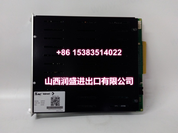
Installation Pitfalls & Guide
❗ Output Load Sizing: The 0.5A per channel limit is real. If you’re driving a large solenoid or relay coil, check the inrush current. A 2A inrush can trigger the protection circuit even if the steady-state draw is 200mA. Use an interposing relay for high-current loads.
❗ Wiring Polarity: This module supports both sinking and sourcing, but you must configure it correctly in software. Wiring a sourcing output to a sinking input without proper termination will cause erratic behavior. Check the DIP switches or software config before applying power.
❗ Backplane Power Draw: Digital output modules draw significant 24VDC when outputs are energized. If you’re driving multiple solenoids, calculate the total load. A sagging 24V rail can cause inputs to chatter or outputs to drop out.
Replacement SOP:
- Pre-Install: Tag every wire; photograph the terminal layout before pulling.
- Removal: Release the top and bottom latches simultaneously; pull straight out.
- Install: Verify the keying tab aligns; push until you hear the dual click.
- Power-On: Apply backplane power; wait for the “Module OK” LED before enabling outputs.
Technical FAQ
Q: Can I mix IOP310 and IOP301B modules in the same rack?
A: Yes, the IOP300 backplane supports mixed digital and analog cards. Just ensure your configuration software matches the slot assignment to the physical card type. The backplane doesn’t auto-detect; you have to tell it what’s where.
Q: Why is my output flickering even with a solid input?
A: Check for ground loops. If the field ground and module ground aren’t at the same potential, you’ll see noise on the inputs. Verify your shield grounding and ensure the 24VDC supply is properly referenced. Also check for loose terminal connections.
Q: Is this module compatible with third-party DCS systems?
A: The IOP310 is designed for Metso DCS backplanes. While the digital signals are standard, the backplane communication protocol is proprietary. You can’t plug this into a Siemens or Allen-Bradley rack without a gateway. Stick to the OEM ecosystem for this card.
Q: What does the “Short Circuit” diagnostic actually detect?
A: It monitors the output current. If it exceeds 0.6A, the module flags a short and shuts down that channel to prevent damage. Note: It won’t detect an open load—that just reads as “output off but no current.” You need a separate open-wire test for that.
Q: Do I need to configure the channel direction?
A: Yes. The IOP310 channels are configurable as input or output via software. Make sure you set the direction correctly before applying power. Configuring a channel as output when it’s wired to a sensor can damage the output driver.
Need the terminal block wiring diagram or the Modbus register map for this IOP310? I can pull those docs for you.




