
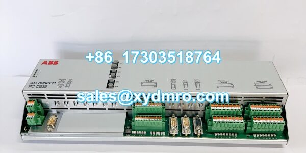
Product Core Brief
- Model: PCD235B101 (3BHE057901R0101)
- Brand: ABB
- Series: AC 500 / Excitation Control
- Core Function: Controls generator excitation current magnitude and regulation to ensure stable power quality.
- Product Type: Excitation Driver Unit / Digital Output Module
- Key Specs: 16 Channels | 2A Max per Channel | 24V DC
- Condition: New Surplus / Original OEM
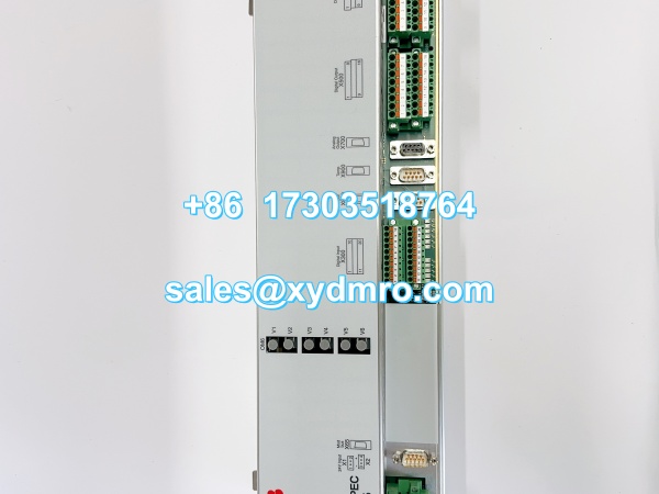
PCD235B101 3BHE032025R0101
Key Technical Specifications
- Order Code: 3BHE057901R0101
- Output Capability: 16 Channels
- Max Output Current: 2A per channel at 24V DC
- Communication Protocols: Modbus RTU, Profibus DP, Ethernet
- Power Supply: 24V DC (±10% to ±20% tolerance)
- Operating Temperature: -20°C to +60°C
- Mounting Method: Standard DIN Rail
- Diagnostics: Built-in fault detection mechanisms
- Application: Generator Excitation Systems
Product Introduction
This unit acts as a dedicated excitation driver for synchronous generators, regulating excitation current to maintain grid voltage stability. It doubles as a high-capacity digital output module within industrial automation networks.
Engineers rely on this board’s built-in fault detection to catch short circuits before they damage the exciter. The 2A per-channel drive capability eliminates the need for external interposing relays, saving panel space and reducing wiring points.
QA & Testing SOP
Every ABB PCD235B101 gets a full bench workout before it ships. We start with a visual inspection under magnification, checking for cold solder joints and verifying all 16 output channel traces are intact. The board is then seated in an OEM test rack to validate firmware and cold-boot stability.
We run a full-scale load test, pulling 2A from each channel simultaneously while monitoring for thermal drift on the output transistors. Communication is verified by cycling through Modbus and Profibus frames. Finally, each unit gets anti-static packaging and anti-counterfeit lot verification.
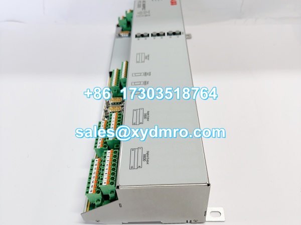
PCD235B101 3BHE032025R0101
Installation Pitfalls & Guide
❗ Heat Dissipation: At 2A per channel, this module generates real heat. Ensure at least 10mm clearance on both sides for airflow; stacking it against a hot power supply will trigger thermal shutdowns.
❗ Grounding Star Point: Connect the 24V DC common to a clean star ground. Ground loops through the excitation output will cause erratic generator voltage and false fault alarms.
❗ Backplane Connector Alignment: The DIN rail latch must click audibly. A half-millimeter gap on the bus connector causes intermittent output drops that mimic field wiring faults.
Replacement SOP:
- Pre-Install: Back up excitation parameters and verify firmware revision matches the existing controller.
- Removal: De-energize the 24V DC supply; wait 60 seconds for output capacitor discharge.
- Install: Slide the onto the DIN rail; engage the locking lever until it seats fully.
- Power-on Test: Verify LED status; command each output channel individually before closing the field breaker.
Technical FAQ
Can I use this as a standard DO module without the excitation function?
Yes. The 16 channels operate independently as 24V DC digital outputs. You can use the OEM engineering tool to disable the excitation control blocks and treat it as a general-purpose output module. Just remember the 2A per-channel limit is hard; don’t exceed it.
Is this compatible with older AC 500 CPUs?
Generally yes, but verify the firmware compatibility matrix first. The 3BHE057901R0101 order code indicates a specific hardware revision. Mixing older CPU firmware with newer output modules can cause communication timeouts on the Profibus DP bus.
Why does the price vary between suppliers?
Testing rigor varies wildly. Some sellers ship pulled boards with zero validation. We load-test every channel at full 2A and verify communication protocol compliance. You’re paying for a guaranteed functional unit, not a lottery ticket.
What happens if one output channel shorts?
The built-in diagnostic will flag the fault and shut down that specific channel to protect the rest of the module. However, repeated short circuits will eventually degrade the output stage. Always use properly rated fuses on field wiring.
Do I need special tools for configuration?
You need the OEM engineering software with the excitation control library licensed. Standard PLC programming tools won’t expose the voltage regulator PID parameters or the field current limiting thresholds stored on this module.




