
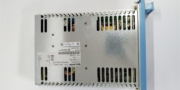
Product Core Brief
- Model: FC-PSU-240516
- Brand: Honeywell
- Series: FSC (Fail Safe Controller) / Experion Safety
- Core Function: Provides stable, redundant 24VDC power to FSC system modules with integrated fault diagnostics.
- Product Type: Power Supply Unit (PSU) / Power Controller Module
- Key Specs: 24 VDC Output | 5A Max | Dual Redundant Input | >85% Efficiency
- Condition: New Original (New Surplus)
Product Introduction
The is a high-reliability power supply module designed for the Honeywell FSC and SIS (Safety Instrumented System) architectures. It converts standard industrial AC or DC input voltages into a highly regulated 24VDC output to safely drive controllers, I/O cards, and field devices.
Engineered for critical process environments, this module features a dual power redundant architecture with automatic failover. It includes comprehensive internal protection (overcurrent, short circuit, and surge protection) and utilizes 6 diagnostic LEDs to provide real-time visual feedback on power status and system health.
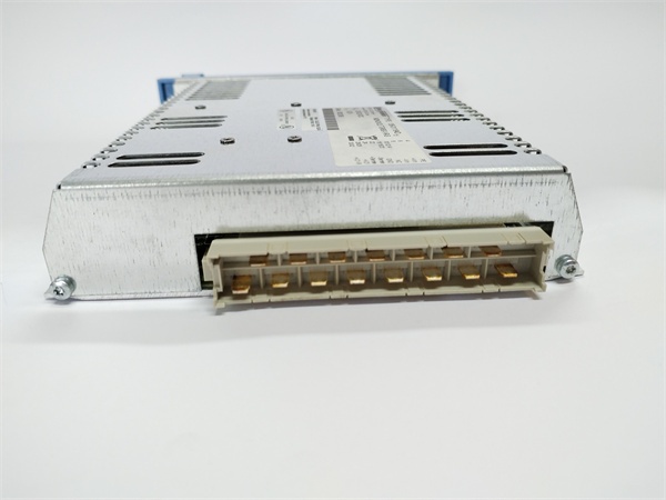
Key Technical Specifications
| Parameter | Value |
|---|---|
| Module Type | Power Supply Unit (PSU) |
| Output Voltage | 24 VDC |
| Max Output Current | 5 A |
| Input Voltage Range | 90–264 VAC or 24 VDC |
| Redundancy | Dual Power Redundant Architecture |
| Efficiency | > 85% |
| Output Ripple & Noise | < 1% |
| Diagnostics | 6x Dual-Color LED Indicators |
| Protection | Overcurrent, Short Circuit, Surge |
| Operating Temp | -20 °C to +60 °C |
Quality Control Process (Engineer’s Perspective)
We don’t just box these and ship them. Here is our actual bench test workflow.
- Incoming Verification: We verify the serial number against Honeywell’s traceability records. A visual inspection checks the aluminum housing for impact damage and ensures the terminal blocks are free of corrosion.
- Live Functional Test: We mount the unit in a live FSC test rack. We apply nominal input voltage and verify the 24VDC output stability under a simulated 5A load using an electronic load tester.
- Electrical Parameter Test: We perform a 500 V Megger test between the input terminals, output terminals, and chassis. Insulation resistance must exceed 10 MΩ. Ground continuity is verified.
- Protection & Diagnostic Test: We intentionally inject an overcurrent condition to verify the internal protection trips correctly. We also verify that the 6 diagnostic LEDs illuminate in the correct sequence during startup and fault conditions.
- Final QC & Packaging: The module is sealed in an anti-static bag with silica gel. A QC sticker showing the test date and technician initials is applied to the exterior.
Replacement Pitfall Guide
Field replacements on power systems are unforgiving. Watch out for these traps.
- Redundancy Handshake Failure: ❗ Critical. If your system uses dual FC- modules for redundancy, ensure the new module’s firmware and internal settings match the existing unit. Mismatched parameters can prevent the automatic failover handshake from completing.
- Input Voltage Misconfiguration: Verify whether your field wiring is supplying 90-264 VAC or 24 VDC before energizing. Applying the wrong input type can instantly destroy the internal rectifier circuit.
- Terminal Torque: Power modules carry high currents. Ensure all input and output terminal screws are torqued to the manufacturer’s specification. A loose connection will cause localized heating, leading to intermittent brownouts that mimic module failure.
- Load Calculation: Verify your total system load does not exceed the 5A continuous rating. Always maintain at least 20% headroom on your power supply to accommodate inrush currents during system boot.
- ESD Damage: The internal microcontroller and diagnostic circuits are highly sensitive to electrostatic discharge. Always wear a grounded wrist strap when handling the bare PCB.
Keep these in mind and you’ll cut 90% of rework time.
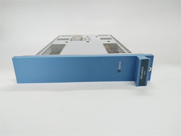
Compatibility Matrix & Benchmarks
Compatibility
- Honeywell FC- Rev A → FC- Rev B : Direct Replacement — Verify firmware compatibility with FSC CPU.
- Honeywell FC-TPSU-2430 → FC- : Needs Adaptation — Verify current capacity and physical form factor differences.
Benchmarks
- Redundant Switchover: 0 ms (zero interruption during primary module failure)
- Power-On to Ready: < 3 s (from AC applied to OK signal assertion)
Need the LED diagnostic code chart for the ? I can pull up the troubleshooting matrix so you can instantly decode the 6 status LEDs during commissioning or fault isolation.




