
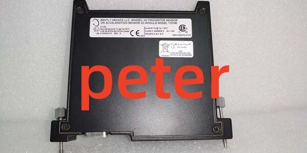
Product Core Brief
- Model: 170180‑01‑05
- Brand: BENTLY
- Series: FieldMonitor 1701 System
- Core Function: Dual‑channel external transducer I/O delivering ‑18 VDC excitation for legacy proximity probes, used for shaft vibration, thrust and gap measurement.
- Product Type: Dual‑Channel ‑18 VDC Proximitor External Transducer I/O Module
- Key Specs: 2 proximitor input channels | ‑18 VDC sensor excitation | Single‑slot terminal‑base mounting ⚠️ EOL — limited stock remaining
Product Introduction
BENTLY 170180‑01‑05 occupies one slot in a FieldMonitor terminal base. It supplies ‑18 VDC excitation specifically for older‑generation eddy‑current proximity probes that cannot run off‑24 VDC drive voltages.
Compared to the 170180‑01‑00 (‑24 V variant), this unit cannot drive accelerometers. It is purpose‑built for legacy probe retrofit jobs —though your mileage may vary if you pair it with modern‑24 V probes.
Key Technical Specifications
| Parameter | Value |
|---|---|
| Channel Count | 2 proximity‑probe input channels |
| Transducer Excitation | ‑18 VDC, fixed output |
| Supported Sensors | Legacy eddy‑current proximity probes requiring ‑18 V drive |
| Incompatible Sensors | Accelerometers,‑24 V proximitor probes |
| Host Hardware | FieldMonitor 1701 terminal‑base assembly |
| Mounting | Single‑slot insertion into terminal base; DIN‑rail via base |
| Hot‑Swap Support | Yes (FieldMonitor base compliant) |
| Operating Ambient Temperature | ‑40 °C to +70 °C |
| Relative Humidity | 5‑95 %, non‑condensing |
| Module Current Draw | 20 mA max (transducer load excluded) |
| Physical Weight | 0.27 kg |
| Country of Origin | United States |
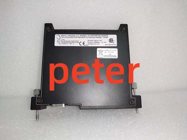
BENTLY 170180‑01‑05
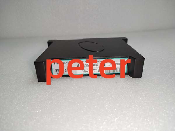
BENTLY 170180‑01‑05
Quality Control Process (Engineer’s Perspective)
- Incoming Verification: Source traceability, serial number anti‑counterfeit check, visual inspection (no corrosion/scratches). Check edge connector pins for bending or wear.
- Live Functional Test: Power‑on self‑check, base comms handshake, continuous load run >24 hrs with temp logging. Capture LED status snapshots every two hours.
- Electrical Parameter Test: Insulation resistance (500 V Megger, >10 MΩ), ground continuity. Flag any resistance drift below threshold.
- Firmware Verification: Read/record firmware version, photograph DIP switch/jumper settings. Well, technically it supports custom gap alarm thresholds, but only on firmware v3.1+.
- Final QC & Packaging: Anti‑static bag seal, QC Passed label with date. Matching terminal hardware bagged alongside the unit.
Replacement Pitfall Guide
❗ Firmware Mismatch: The unit will reject custom gap‑alarm configurations if host terminal‑base firmware falls below minimum revision. Older firmware locks to factory preset ranges.❗ DIP Switch / Jumper Misconfiguration: Factory defaults rarely match field settings. Pay close attention to channel input‑mode jumpers on the module edge connector.❗ Terminal / Cable Incompatibility: Pin definitions shift across hardware revisions. Cross‑reference wiring drawings before connecting legacy proximity probe extension cables. Never mix‑18 V and‑24 V module types on the same probe.❗ Power Supply Mismatch: Recalculate total terminal‑base power with 20% headroom. Adding multiple transducer‑I/O modules can push marginal 24 VDC supplies over their continuous rating.❗ ESD Damage: Use anti‑static mat; caution in dry environments. Static discharge can degrade transducer excitation circuitry with no visible physical damage.
Keep these in mind and you’ll cut 90% of rework time.
Compatibility Matrix & Benchmarks
- Scan cycle: 11 ms (simulated load, 2 active proximitor input channels)
- Comms throughput: 500 kbps (FieldMonitor proprietary backplane bus)




