
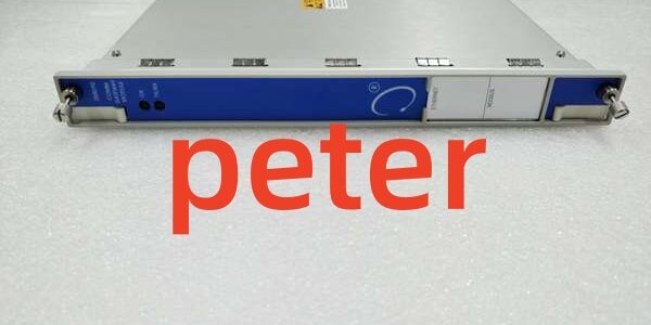
Product Core Brief
- Model: 1701/15
- Brand: BENTLY
- Series: FieldMonitor 1701 System
- Core Function: Conditions dual proximity probe inputs for shaft radial vibration and thrust‑position measurement with configurable alarm thresholds.
- Product Type: Dual‑Channel Proximitor Input Monitor Module
- Key Specs: 2 proximity probe channels | 4‑20 mA scalable analog output | DIN‑rail mountable ⚠️ EOL — limited stock remaining
Product Introduction
BENTLY 1701/15 fits into the 1701 FieldMonitor terminal base to process eddy‑current proximity probe signals for rotating machinery protection. It delivers processed measurement data and alarm status to plant DCS systems.
Unlike full‑size 3500 rack monitors, this unit uses compact DIN‑rail packaging. It achieves ±0.30 % full‑scale measurement accuracy across both channels —though your mileage may vary when using non‑Bently extension cable assemblies.
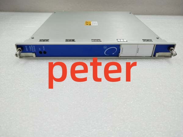
BENTLY 1701/15

BENTLY 1701/15
Key Technical Specifications
| Parameter | Value |
|---|---|
| Channel Count | 2 independent proximity probe input channels |
| Supported Probes | 3300‑XL series eddy‑current proximity transducers |
| Measurement Types | Radial vibration, thrust / axial position, gap voltage |
| Accuracy | ±0.30 % full‑scale |
| Analog Output | Isolated 4‑20 mA per channel for DCS interface |
| Power Supply | 18‑32 V DC, ≤5 W power draw |
| Mounting | DIN‑rail via 1701 terminal base assembly |
| Hot‑Swap Support | Yes (FieldMonitor base compliant) |
| Operating Ambient Temperature | ‑40 °C to +70 °C |
| Relative Humidity | 5‑95 %, non‑condensing |
| Physical Weight | 0.34 kg |
| Country of Origin | United States |
Quality Control Process (Engineer’s Perspective)
- Incoming Verification: Source traceability, serial number anti‑counterfeit check, visual inspection (no corrosion/scratches). Check edge connector pins for bending or wear.
- Live Functional Test: Power‑on self‑check, base comms handshake, continuous load run >24 hrs with temp logging. Capture LED status snapshots every two hours.
- Electrical Parameter Test: Insulation resistance (500 V Megger, >10 MΩ), ground continuity. Flag any resistance drift below threshold.
- Firmware Verification: Read/record firmware version, photograph DIP switch/jumper settings. Well, technically it supports gap alarm thresholds, but only on firmware v2.7+.
- Final QC & Packaging: Anti‑static bag seal, QC Passed label with date. Matching terminal hardware bagged alongside the unit.
Replacement Pitfall Guide
❗ Firmware Mismatch: The unit will reject custom alarm threshold settings if host terminal‑base firmware falls below minimum revision. Older firmware locks to factory preset ranges.❗ DIP Switch / Jumper Misconfiguration: Factory defaults rarely match field settings. Pay close attention to probe‑sensitivity jumpers on the module edge connector.❗ Terminal / Cable Incompatibility: Pin definitions shift across hardware revisions. Cross‑reference wiring drawings before connecting proximity probe extension cables.❗ Power Supply Mismatch: Recalculate total base power with 20% headroom. Adding this module can push marginal 24 V DC supplies over their continuous rating.❗ ESD Damage: Use anti‑static mat; caution in dry environments. Static discharge can degrade probe excitation circuitry with no visible physical damage.
Keep these in mind and you’ll cut 90% of rework time.
Compatibility Matrix & Benchmarks
- Scan cycle: 13 ms (simulated load, 2 active proximity‑probe input channels)
- Comms throughput: 500 kbps (FieldMonitor backplane bus)




