
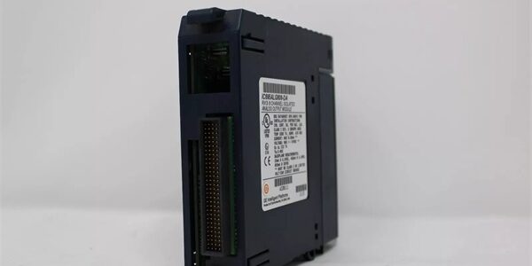
Product Core Brief
- Model:
- Brand: GE Fanuc / GE
- Series: Series 90-30 PLC
- Core Function: Executes user control logic, manages local and remote I/O racks, provides dual independent RS232 serial ports for programming, HMIs and Modbus devices.
- Product Type: Mid-Range CPU Processor Module
- Key Specs: 25 MHz 80386EX | Max 240KB configurable user memory | Dual onboard RS232 serial ports Note: Discontinued legacy hardware; factory new stock extremely limited, surplus and refurbished units widely traded. The -DF suffix denotes a specific factory PCB hardware revision. Hot swapping is not supported on Series 90-30 backplanes.
Key Technical Specifications
- Processor: 25 MHz Intel 80386EX
- Boolean Scan Speed: 0.22 ms per 1K boolean contact logic
- User Memory: Up to 240KB configurable memory (Firmware Rev9.0 and newer; older firmware limited to 80KB)
- Onboard Interfaces: Two independent RS232 serial ports (Port 1 / Port 2)
- Supported Serial Protocols: SNP/SNPX, Modbus RTU Master / Slave
- Auxiliary Serial: SNP/SNPX via compatible rack power supply RS485 terminal
- Maximum System Scale: 8 baseplates (1 main rack + up to 7 expansion/remote racks)
- Discrete I/O Capacity: 2048 %I inputs, 2048 %Q outputs
- Analog Register Space: Configurable up to 32,640 words for %AI / %AQ / %R
- Backplane Power Draw: 890 mA @5 VDC
- Battery-backed real-time clock
- Operating Temperature: 0°C to 60°C horizontal cabinet mounting
- Storage Temperature: -40°C to 85°C
- Form Factor: Single-width Series 90-30 rack slot
- Compatible Programming Software: Proficy Machine Edition, Logicmaster 90
- Network Expansion: Requires separate communication modules (CMM321 etc.) for Ethernet, Genius bus
Product Introduction
This unit is a mid-tier processor for Series 90-30 control systems. Dual built-in RS232 ports enable simultaneous connections to programming terminals, local HMIs or serial field devices without adding extra communication modules.
Memory partitioning allows engineers to allocate space for user program logic, analog registers and discrete data tables. It is widely deployed for machine control and plant retrofit projects that rely on serial communications and do not require integrated onboard Ethernet.
QA & Testing SOP (Transparency Building)
- Incoming Inspection: Verify part marking and -DF revision suffix. Inspect backplane edge pins for bending or corrosion; check port connectors and housing for physical damage.
- Live Testing: Mount into validated Series 90-30 rack, apply nominal rack power. Load representative user program, establish serial communications, run continuous 24-hour logic cycle testing.
- Electrical Testing: Use Fluke 115 to monitor backplane 5VDC rail stability. Insulation resistance testing must exceed 10MΩ between circuit traces and chassis protective ground.
- Firmware/Config Backup: Record installed CPU firmware version. Capture photos of front panel labels before erasing resident configuration.
- Final QC & Packaging: Place unit inside anti-static shielding. Attach dated QC test tag confirming program execution and serial port communication validation prior to shipment.
Installation Pitfalls & Guide (Engineer to Engineer)
❗ No Hot Swap Support: Series 90-30 backplanes lack hot-swap bus logic. Live removal crashes all rack I/O and risks permanent backplane trace damage. Full rack power shutdown mandatory. ❗ Revision Suffix Awareness: The -DF hardware revision contains component screening differences. Mechanically interchangeable with other CPU351 variants, but complete post-replacement I/O and communication validation is required. ❗ Serial Port Wiring Risk: pinout follows GE proprietary definition. Generic straight-through PC cables will fail communications; use validated GE serial cables. ❗ Firmware Version Boundary: If firmware older than Rev9.0, maximum usable memory is limited to 80KB. Upgrading firmware unlocks full 240KB memory capacity. ❗ ESD Dangers: Un-grounded handling can damage serial transceivers and memory circuits. Static faults often appear as intermittent serial communication dropouts after commissioning. ❗ Power Budget Oversight: This module draws 890mA @5VDC. Recalculate total rack power consumption to avoid overloading the Series 90-30 power supply.
Replacement Guide:
- Pre-install: Activate lockout-tagout on rack power; back up the complete user program and hardware configuration. Photograph serial wiring connections.
- Removal: Unplug serial cables, unlatch module and slide straight out without twisting backplane connectors.
- Install: Seat new unit fully into designated CPU slot, lock latches, reconnect cabling.
- Power-on Test: Restore rack power, monitor CPU status LEDs, download saved program and verify I/O and serial port communications.
FAQ (Frequently Asked Questions)
Q: Does this module support hot swapping? A: No. Series 90-30 architecture does not implement hot-swap functionality. Complete rack power shutdown is required before removing or installing the unit.
Q: What is the difference between and IC693CPU351-HT? A: Base catalog number defines identical core CPU functionality. -DF and -HT are different PCB hardware revisions. Mechanically interchangeable, but always perform full communication and logic testing after cross-revision replacement.
Q: Does this CPU have built-in Ethernet? A: No. There is no onboard Ethernet port. Network connectivity requires installing separate communication modules such as IC693CMM321.
Q: Can this CPU be installed inside PACSystem RX3i racks? A: No. Form factor, backplane signaling and firmware are exclusive to Series 90-30 chassis. It cannot operate within RX3i systems.
Q: What happens if power is lost during a firmware upgrade? A: The CPU can become unbootable. Maintain stable rack power and retain a spare processor before initiating any firmware flash operation.
Q: Can the two ports run independent protocols at different baud rates? A: Yes. Each serial channel can be configured separately for SNP programming or Modbus RTU communication.
Q: Will saved program files load directly onto a replacement unit? A: Program logic imports without modification. Serial port parameters and any external comm module settings must be reconfigured manually after replacement. Always complete a full I/O validation test.




