
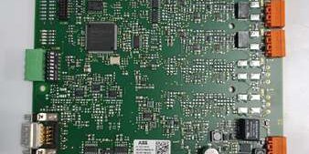
Product Core Brief
- Model: UFC911B101, OEM part number 3BHE009631R0041
- Brand: ABB
- Series: UNITROL 5000 / Advant OCS static excitation system DIN rail signal conditioning unit
- Core Function: Conditions multi-channel 4–20mA / ±10V analog transducer signals for generator voltage, stator current and winding temperature measurement and transmits data via dual bus interfaces
- Product Type: DIN rail mounted passive analog signal conditioning & communication interface PCB
- Key Specs: Multi galvanically isolated analog loops | Masterbus300 + Modbus RTU dual bus | 24VDC SELV supply
- Note: Full platform end-of-life; factory sealed new assemblies and fully cyclic load-tested surplus available for thermal, hydro and cogeneration power plant cabinet maintenance
Key Technical Specifications
- Analog input compatibility: 4–20mA two-wire loops, ±10V voltage transducers
- Per-channel isolation: 1500 VAC reinforced galvanic isolation between field wiring and internal logic
- Bus communication: ABB Masterbus300 rack backplane, RS485 Modbus RTU 9.6k–19.2k baud
- Auxiliary operating supply: 24 VDC ±10% SELV, 0.15A continuous draw
- Fault detection logic: Detects open transducer wires, short-circuit and reversed loop polarity
- Diagnostic indicators: Multi-color front LED array for power, bus communication and individual channel fault states
- Mechanical mounting: Standard 35 mm EN 50022 DIN rail clip-in housing
- Enclosure rating: IP20 for interior cabinet installation
- PCB surface treatment: ISA G3 conformal coating standard for coastal high-humidity substation environments
- Operating ambient temperature: 0°C to +60°C sealed cabinet; storage -40°C to +85°C
- Humidity tolerance: ≤75% RH non-condensing below 55°C
- Net assembly weight: 0.28 kg
- Overall dimensions: 118 mm H × 46 mm W × 122 mm D
- Compliance standards: IEC 60255 power protection, EU RoHS 2011/65/EU, CE certified
Product Introduction
This DIN rail signal conditioning unit receives raw analog transducer signals from generator field equipment, isolating and linearizing measurements before sending data to the main UFC760 series excitation control board via Masterbus300. Passive signal conditioning circuits maintain consistent analog conversion accuracy without firmware tuning, and dual bus interfaces enable redundant communication paths to avoid single-point data loss for safety-critical excitation control loops. Front channel fault LEDs allow technicians to identify broken measuring cables without multimeter testing.
QA & Testing SOP
- Incoming Inspection: Cross-reference serial number against ABB UNITROL excitation spare asset database to filter counterfeit assemblies; inspect analog terminal blocks, Modbus D-Sub9 port and front LED array with a 10x magnifier for thermal discoloration or pin corrosion; log serial numbers for full generator protection traceability records.
- Live Testing: Mount the unit on a DIN rail test bench paired with a UFC760BE143 main excitation controller and calibrated resistance/current signal simulators; supply rated 24VDC auxiliary power; run a continuous 24-hour cycle test including wire break fault injection, full analog range sweeps and Modbus RTU throughput validation.
- Electrical Testing: Use a Fluke 115 multimeter to verify ≥10MΩ isolation between each analog channel and cabinet chassis ground; measure PE continuity resistance below 0.5Ω.
- Firmware/Config Backup: Photograph front LED fault mapping and OEM maximum analog cable length limits printed on the unit housing for field wiring reference.
- Final QC & Packaging: Wipe plastic housing with static-dissipative microfiber cloth; cap analog and Modbus D-Sub9 terminals with insulating dust covers; seal the assembly inside a shielding ESD bag, attach a printed QC tag with full 24-hour analog signal cycle test timestamp, then pack into foam lined transit cartons.
Installation Pitfalls & Guide
❗ Reversed 4–20mA transducer wiring locks channel output under range: Swapped loop wires trigger permanent fault state until wiring correction and full cabinet power cycle completion. ❗ Unshielded analog cabling creates periodic measurement drift: Cable runs longer than 10m near variable frequency drives induce noise that generates false temperature/voltage alarms in the DCS. ❗ Over-torqued terminal lugs fracture internal PCB traces: Fan vibration loosens unproperly secured wiring during continuous plant operation, causing intermittent analog dropout. ❗ ESD discharge destroys internal signal conditioning ICs: Bare finger contact with PCB measuring traces shifts linearity outside ±0.1% tolerance, requiring bench recalibration before site deployment. ❗ Hot-swap energized 24VDC supply corrupts Masterbus300 differential clock signals: Removing the unit under live power forces the main excitation controller to cold restart, removing active generator voltage regulation.
4-step replacement guide
- Pre-install: Lock out and tag cabinet 24VDC auxiliary power supply breaker; wait 10 minutes for internal logic capacitors to fully discharge; don ESD wrist strap; capture photos of analog transducer field wiring and Modbus D-Sub9 communication layout.
- Removal: Disconnect all analog measuring wires and Modbus cables channel by channel following captured photos; release the DIN rail retention clip, slide the old hardware horizontally off the rail without bending terminal lugs.
- Install: Clip the new unit firmly onto the original DIN rail position; re-terminate all analog transducer wiring matching recorded polarity sequence to OEM torque specifications.
- Power-on Test: Restore 24VDC auxiliary power; confirm steady green RUN LED and active BUS communication indicator; inject calibrated 4–20mA signals to validate linear measurement transfer to the UFC760 main board; simulate a broken sensor wire to confirm red fault LED activates and locks the channel at under-range value.
FAQ
Q: Can this unit operate without a paired UFC760 main excitation controller? A: It will condition analog signals and hold linear output values, but all voltage regulation and synchrocheck interlock logic will remain offline. A matched main control board is required to execute automatic generator excitation trimming and grid paralleling sequences. Q: Is hot-swapping supported while cabinet 24VDC auxiliary power remains energized? A: It is not supported. The live Masterbus300 differential bus carries high-speed control frame data; unplugging the unit creates voltage transients that disrupt bus timing and force the excitation controller to cold restart, disabling real-time generator monitoring. Full power lockout and capacitor discharge wait time are mandatory before disassembly. Q: What warranty coverage applies to stocked units? A: Factory-new original analog signal conditioning units carry a 12-month OEM warranty covering multi-channel isolation transformers, analog conditioning circuits and front diagnostic LED arrays. Continuity-tested surplus units come with a 6-month warranty. Damage from reversed transducer wiring, unshielded field cabling or ungrounded ESD handling voids all coverage. Q: What hardware replaces this unit for new power station builds? A: ABB UFC760BE143 integrates analog signal conditioning directly on the main excitation control board, eliminating separate DIN rail signal modules. This hardware is only approved for one-to-one maintenance replacement of pre-2020 UNITROL 5000 Advant OCS excitation racks. Q: Will linear calibration offset values shift after full cabinet power outage? A: All analog conversion characteristics rely on passive PCB resistor networks, so power loss does not alter signal linearity. No non-volatile memory stores custom tuning data on the hardware, so no parameter reconfiguration is required post-replacement beyond verifying physical wiring polarity. Q: What are the most common failure modes for a faulty unit? A: Persistent channel fault LED with correct transducer wiring, fixed under-range analog output from degraded isolation transformers, intermittent Modbus RTU packet loss under cabinet temperature fluctuation, complete loss of Masterbus300 communication to the main excitation controller, and zero linear current variation when transducer resistance changes.




