
Product Core Brief
- Model: SA801F, official OEM codes: 3BDH000011R1, 3BSE008508R1
- Brand: ABB Hitachi Energy
- Series: ABB Freelance AC800F distributed control system dedicated rack power supply module
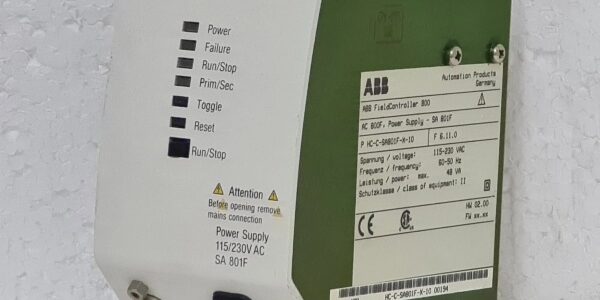
- Core Function: The mandatory primary power module installed in the dedicated P power slot of AC800F controller rack. It converts universal 115–230VAC mains input into two stabilized low-voltage DC rails (3.3VDC / 5VDC) to power the PM803F CPU board, Ethernet communication modules and PROFIBUS fieldbus cards inside the controller rack. It integrates built-in EMC filtering, 20ms power failure hold-up buffer, full hardware protection and front-panel system operation buttons, status LEDs and diagnostic service port for DCS commissioning and fault diagnosis.
- Product Type: Rack-mounted DCS controller primary power supply module
- Key Specs: Auto-adjusting 88–264VAC wide mains input; dual isolated DC outputs (3.3V 5A, 5V 5A, total 26.5W); minimum 20ms energy backup during mains drop-out; short-circuit, overload, overvoltage and reverse input protection; exclusive Slot P mounting only; front RUN/FAULT LED indicators + local controller operation pushbuttons
- Note: Mature standard DCS power module still in active mass production; factory-sealed original modules and fully bench-tested surplus units are widely supplied for thermal power plants, chemical processing, water treatment and metallurgical industrial Freelance AC800F system maintenance and new project construction. Cannot be interchanged with higher-power SA811F variant.
Key Technical Specifications
| Parameter | Value |
|---|---|
| Full OEM Article Number | 3BDH000011R1 / 3BSE008508R1 |
| AC Mains Input Range | 88 VAC ~ 264 VAC auto-sensing (nominal 115 / 230 VAC, 47–63 Hz) |
| Rated Input Apparent Power | 63 VA |
| Input Current | 541 mA @ 115 VAC; 275 mA @ 230 VAC |
| DC Output Channel 1 | 3.3 VDC ±3%, max continuous 5 A |
| DC Output Channel 2 | 5.0 VDC ±3%, max continuous 5 A |
| Total Maximum Output Power | 26.5 W |
| Power Failure Hold-Up Time | ≥ 20 ms continuous stable output when AC mains is lost (NAMUR standard compliant) |
| Built-in Protection Suite | Input overvoltage lockout, output constant current limiting, auto-recovery short-circuit shutdown, input surge EMC filter |
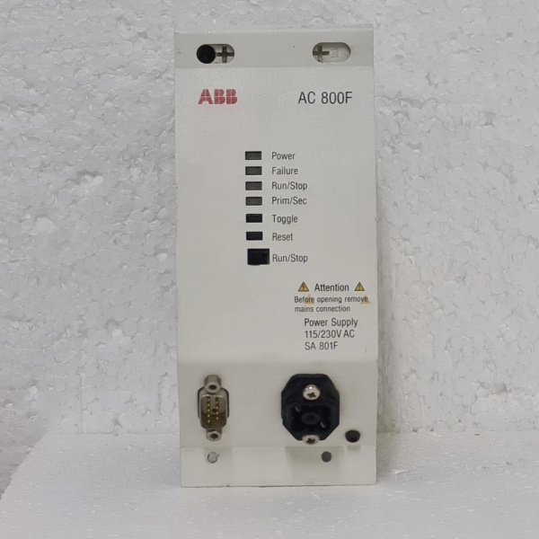
| Front Panel Interfaces | Green RUN LED, orange FAULT diagnostic LED, controller Start/Stop pushbuttons, front service diagnostic port for PC connection |
| Mechanical Installation Rule | Must be installed in the leftmost dedicated P slot of AC800F rack; incompatible with E/F communication slots |
| Enclosure Protection Class | IP20 module housing, fully sealed inside control cabinet |
| Continuous Operating Ambient Temp | -20 °C ~ +60 °C inside DCS cabinet; storage temperature: -40 °C ~ +85 °C |
| Humidity Limit | ≤75% RH non-condensing, indoor control room rated |
| Overall Module Dimensions | 119 mm W × 186 mm H × 135 mm D |
| Net Weight | Approx. 1.0 kg |
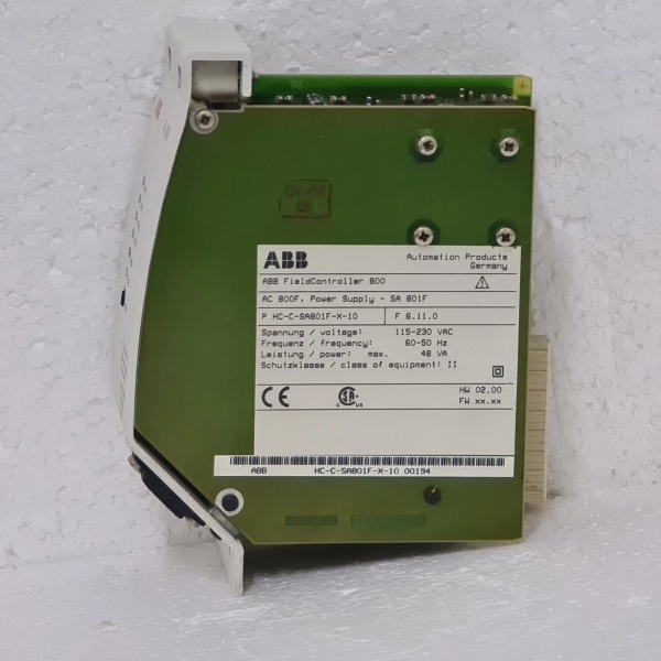
| Compliance Standards | IEC 61010 safety standard for power supplies, IEC 61800 EMC, CE certified, RoHS compliant, NAMUR compliant hold-up performance |
Product Introduction
The is the standard low-power primary power source exclusively designed for single-rack compact AC800F Freelance DCS controllers, acting as the sole power backbone for all core controller hardware including CPU, Ethernet and fieldbus communication cards.Its four core design advantages for process control systems:
- Universal Wide AC Input CompatibilityAuto-sensing mains circuit eliminates manual voltage selector switches, supporting all global industrial AC mains (115V / 230V) with tolerance for ±20% grid fluctuation, greatly simplifying spare part inventory for multi-region factories. Integrated multi-stage EMC filter suppresses high-frequency switching noise generated by MCC drives and breakers to avoid CPU communication crash and data loss.
- Dual Stabilized Isolated Low-Voltage OutputsThe 3.3V rail supplies the core CPU logic chipset, while the 5V rail powers all fieldbus transceivers and Ethernet communication circuits. Independent galvanic isolation between the two DC rails prevents cross-channel interference, ensuring stable high-speed real-time process data transmission to SCADA and field I/O stations.
- 20ms Power Failure Hold-Up Buffer (Critical For DCS Safety)Built-in energy storage capacitors maintain stable DC output for at least 20ms after AC mains loss, allowing the PM803F CPU to complete safe data backup, fault code recording and orderly shutdown logic before power fully collapses, avoiding incomplete alarm/event log loss and unplanned controller hard reset.
- Integrated Local Operation & Diagnostic Front PanelUnlike generic DIN rail power supplies, embeds dedicated controller Start/Stop pushbuttons and a front optical service port. Maintenance engineers can perform online parameter upload/download, fault diagnosis and controller cold restart without opening the cabinet rear wiring compartment. Dual color LEDs clearly indicate normal running status or power circuit/overload faults for rapid troubleshooting.
It is limited to small-to-medium single rack configurations with up to 3 PROFIBUS FI830F fieldbus cards. For multi-rack heavy-load DCS systems requiring higher output power, the upgraded SA811F power module must be selected instead. Without a functional , the entire controller rack will lose all CPU and communication functions, leading to full process control outage.
QA & Testing SOP (Transparency Building)
- Incoming Visual Inspection: Cross-check full part number 3BDH000011R1 and serial number against ABB DCS spare parts database to reject counterfeit mismatched modules; inspect front LED indicators, service port, internal switching power circuit and PCB conformal coating for burn marks, discoloration or connector pin damage; record serial numbers and production batches for full traceability.
- Full Rack Linkage Bench Test: Mount into standard P-slot test rack, connect matched PM803F CPU and multiple FI830F PROFIBUS slave cards; supply variable 88–264VAC mains input, run 24-hour cyclic full-load testing, simulate AC mains momentary dropout to verify ≥20ms hold-up performance, test overload/short-circuit protection auto-lockout and recovery, confirm fault LED trigger and diagnostic port communication function normally.
- Electrical Insulation Test: Use insulation resistance tester to confirm isolation resistance ≥ 10 MΩ between AC high-voltage input circuits and low-voltage 3.3V/5V DC output rails; test chassis ground continuity resistance below 0.5 Ω.
- Hardware Record Backup: Record module hardware revision, photograph front panel button definitions and rack slot mounting positioning rules for field commissioning reference.
- Final QC Packaging: Wipe module housing with anti-static microfiber cloth, cover front service port with insulating dust cap, place the unit into independent ESD shielding bag, attach unified printed QC test tag with technician ID and full 24-hour full-load test runtime timestamp, then pack into foam shockproof carton for long-distance industrial plant transportation.
Installation Pitfalls & 4-Step Replacement Guide
Common Installation Hazards
❗ Strict Slot Restriction Risk: can only be inserted into the leftmost dedicated P power slot; forced insertion into E (Ethernet) or F (fieldbus) slots will physically damage the rack backplane and module connector pins.❗ Live Mains Disassembly Hazard: The module connects directly to dangerous 230VAC mains input circuits; full lockout/tagout of rack AC power and 5-minute internal capacitor discharge waiting time are mandatory before extraction to avoid electric shock.❗ Overload Load Matching Error: Do not connect more than 3 PROFIBUS FI830F communication cards to one power rail; excessive total current will trigger persistent overload fault lockout and continuous controller restarts.❗ ESD PCB Damage Risk: Wear certified anti-static wrist strap during all disassembly and installation work; bare hand contact with internal switching chips and DC output regulation circuits permanently impairs voltage stabilization accuracy and hold-up function.❗ Mains Wiring Polarity Irrelevance But Torque Control: AC input wiring has no positive/negative polarity, but under-tightened terminal lugs create high contact resistance, leading to module overheating and frequent power flicker faults.
4-Step Rack Module Replacement Guide
- Pre-install Preparation: Lock out and tag out the AC mains power supply feeding the controller rack, wait minimum 5 minutes for internal power supply capacitors to fully discharge, wear ESD wrist strap, photograph AC mains input terminal wiring and rack backplane connector sequence of the module in the P slot.
- Removal Operation: Unplug the front service port cable (if connected), unlock the rack module front latch, slide the module fully out of the P slot rack backplane connector.
- Installation & Wiring: Align the new module with the leftmost P slot rail, slide fully inward until the latch clicks locked; re-terminate AC mains input wiring to standard torque values following photographed terminal sequence, confirm no loose wire strands cause short-circuit risks.
- Power-on Commissioning Test: Restore rack AC mains power, observe front green RUN LED steady on and orange FAULT LED off; boot PM803F CPU and verify all Ethernet/PROFIBUS communication cards initialize normally without power fault alarms; simulate brief AC mains power loss to confirm no controller reset or data corruption, upload DCS process data to SCADA to verify stable continuous transmission.
FAQ
Q: What is the key difference between and SA811F?
- : Standard low-power variant, 3.3V/5V each 5A output, total 26.5W; for single small rack with max 3 fieldbus cards.
- SA811F: High-power upgraded version, 3.3V 6.5A / 5V 5.5A, higher total output power; designed for multi-card heavy-load racks with multiple redundant communication modules. The two cannot be cross-replaced without reconfiguring rack load layout.
Q: Can be hot-swapped with rack AC mains energized?Strictly prohibited. The module mates directly with live 230VAC mains terminals and low-voltage CPU power backplane circuits. Live extraction will cause arc flash hazards, permanent backplane burnout and total DCS process outage. Full mains lockout and capacitor discharge are mandatory before replacement.
Q: What warranty applies to stocked modules?Factory-new original DCS power modules carry 12-month official ABB manufacturer warranty covering AC-DC conversion circuits, dual DC output regulation, hold-up energy storage capacitors and front diagnostic interface. Bench-tested surplus modules provide 6-month functional warranty; damage caused by live wiring disconnection, overload sustained short-circuit or ungrounded ESD handling voids all warranty terms.
Q: Has ABB discontinued production?No formal EOL notice issued; remains standard supply for new Freelance compact single-rack DCS projects and legacy plant spare part maintenance. Modern ABB Ability System 800xA DCS adopts redesigned power unit architecture without separate slot modules.
Q: Will DCS control logic and process parameters be lost after replacing ?All CPU motor control curves, interlock logic and historical event logs are stored in the flash memory of PM803F CPU board, independent of the power module. No full parameter backup rewrite is required after replacement; only a short power failure simulation test to verify hold-up function is recommended.
Q: What typical faults indicate a defective module?Common failure symptoms: Persistent orange FAULT LED alarm with normal AC mains input, frequent automatic controller restarts under full load, CPU communication dropout after brief grid voltage fluctuation (failed 20ms hold-up), unbalanced 3.3V/5V DC output voltage leading to CPU crash, no response from front Start/Stop pushbuttons and offline diagnostic service port communication failure.




