
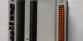
Product Core Brief
- Model: (Complete withdrawable assembly with matched factory draw-out baseplate)
- Brand: ABB Hitachi Energy
- Series: Relion® 615 Dedicated Voltage & Frequency Protection IED, Standard Configuration A
- Core Function: Premium full-feature busbar voltage/frequency monitoring IED for utility distribution, industrial grid and distributed generation (PV/wind) bays. Standard Config A specializes in over/undervoltage, multi-stage frequency protection, anti-islanding, load shedding/restoration, synchro-check, residual earth voltage supervision and 3-channel arc flash detection, equipped with dual PRP redundant Ethernet for digital substation communicationABB Group.
- Product Type: Draw-out Voltage Protection IED Full Assembly (Plug-in Unit + Hardwired Draw-out Baseplate)
- Key Specs: H=100–240V AC/DC universal auxiliary supply | B=Dual PRP redundant Ethernet | U=VT-only voltage measurement hardware | AAD=14DI/12DO full binary I/O | ANB6=Factory licensed 3-channel arc flash + full DG anti-islanding function stack
- Note: Active OEM mass production; factory sealed new full assemblies and fully bench load-tested surplus stocked for urban substations, renewable energy plants, industrial MV switchgear maintenance & new construction.
Key Technical Specifications
| Parameter | Value |
|---|---|
| Full Long Order Code | |
| Auxiliary Power Variant (H) | 100–240 VAC / 48–250 VDC wide-range universal supply; peak 21W power draw |
| Analog Measurement Hardware (U suffix) | 5 galvanic VT voltage channels (3 phase + residual zero-sequence VT), no CT current measurement native (Config A busbar voltage scheme) |
| Binary I/O Layout (AAD expansion) | 14 galvanically isolated digital status inputs; 12 programmable power relay outputs (fast trip, breaker control, load shed interlock, alarm, trip circuit supervision) |
| Core ANSI Protection & Control Function Suite | 27 undervoltage, 59 overvoltage, 59G residual overvoltage earth fault detection, 81O/U multi-stage over/under frequency, anti-islanding LOM loss of mains protection, 74 load shedding & auto-restoration, 25 synchro-check, negative sequence unbalance voltage, 3-channel arc flash detection, breaker failure supervision |
| Onboard Communication Interfaces | Dual 10/100M PRP redundant RJ45 Ethernet (IEC 61850 Ed2.0, GOOSE, MMS, SNTP/IRIG-B time sync); rear RS485 serial port (Modbus RTU / DNP3.0); front optical SPA service port; embedded WebHMI remote accesseero |
| Data Recording Capacity | 500 timestamped SOE event logs; 10 COMTRADE disturbance waveform records for voltage collapse, frequency drift, arc flash and islanding events; permanent grid operation counter storage |
| Draw-out Mechanical Design | Hot-pluggable plug-in unit; baseplate integrated mechanical CT/VT shorting links to eliminate measurement circuit open-circuit hazards during unit swap |
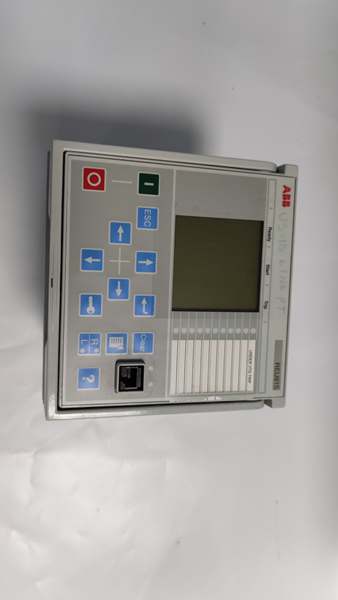
| HMI Interface | Full graphical multi-language LCD, local breaker close/open pushbuttons, customizable LED fault status indicators, editable single-line bay diagram display |
| Front Panel Enclosure Rating | IP54 flush cabinet mount; rear baseplate terminal compartment IP20 |
| Operating Ambient Temp | -10 °C to +55 °C continuous rack operation; short-term storage -40 °C ~ +70 °C |
| Humidity Resistance | <95% RH non-condensing, ISA 71.04 G3 corrosion resistant conformal PCB coating |
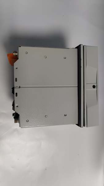
| Mechanical Form Factor | 4U half-width 19-inch draw-out assembly |
| Full Assembly Dimensions | 177 mm W × 177 mm H × 155 mm D |
| Net Assembly Weight (IED + Baseplate) | 3.4 kg |
| Compliance Standards | IEC 60255, IEC 61850, UL508, KEMA type-tested, RoHS, SIL2 capable for grid stability interlocks |
Product Introduction
This is Standard Configuration A premium voltage protection assembly, exclusively designed for busbar supervision and distributed generation grid interconnection, distinct from Config B tap-changer voltage regulation variantseero. Key differentiation: dual PRP redundant Ethernet, factory pre-licensed 3-channel arc flash detection and complete anti-islanding protection for solar/wind power plants.
The withdrawable baseplate integrates dedicated VT shorting links, removing dangerous open-circuit voltage risks during unit replacement—only the plug-in IED is extracted while cabinet VT and control wiring remain permanently terminated on the fixed baseplate. Dual PRP Ethernet ports deliver zero-switchover-time redundant substation communication, supporting high-speed cross-bay GOOSE interlocking for load shedding and DG disconnection without external redundant network switches.
Embedded signal matrix programmable logic replaces external auxiliary relay racks for custom islanding trip sequences, multi-stage load shedding, auto-reconnection and parallel breaker synchro-check interlocks. Disturbance recorders capture pre-fault and post-fault voltage/frequency waveforms to accelerate post-outage root-cause analysis for grid voltage collapse, islanding and arc flash incidents. The front SPA optical port enables offline parameterization without opening live cabinet low-voltage wiring terminalseero.
QA & Testing SOP (Transparency Building)
- Incoming Inspection: Cross-reference full long order code and matching IED/baseplate serial numbers against OEM spare registry to reject mismatched assemblies; inspect graphical LCD, dual Ethernet RJ45 ports, VT terminal block, baseplate shorting links and conformal PCB coating for scratches, salt corrosion or moisture residue; log serial batches for full traceability records. Special verification of arc flash sensor channel and anti-islanding algorithm function.
- Live Full Assembly Testing: Mount IED + baseplate to standard 4U test rack, supply stabilized 220V AC/DC auxiliary power, inject multi-stage VT simulated undervoltage/overfrequency/islanding/arc flash signals, run continuous 24-hour protection element cycling, PRP Ethernet redundant failover stress testing with full event/disturbance log recording validation.
- Electrical Testing: Use Fluke 115 multimeter and insulation resistance tester to verify chassis ground resistance below 0.5Ω and isolation resistance above 10MΩ separating auxiliary power, analog VT measurement and binary control circuit groups; validate mechanical VT shorting link continuity.
- Firmware/Config Backup: Record exact embedded firmware revision via PCM600 configuration tool, photograph baseplate Ethernet DIP address jumpers and RS485 bus switches, export complete voltage/frequency protection curves, load shedding logic and anti-islanding thresholds to encrypted offline storage.
- Final QC & Packaging: Clean front LCD surface with anti-static microfiber cloth, cap SPA optical port and dual Ethernet RJ45 ports with dust protective plugs, separate plug-in IED and baseplate into individual ESD shielding bags, attach unified printed QC test tag with technician ID and full 24-hour runtime timestamp before foam-lined shock-resistant transit carton packaging.
Installation Pitfalls & 4-Step Replacement Guide
Common Installation Risks
❗ Firmware Version Mismatch: Newer firmware builds block anti-islanding calculation and PRP redundant Ethernet communication; cross-check OEM PCM600 software compatibility matrix before downloading grid parameter sets.❗ VT Open-Circuit Measurement Hazard: Always engage baseplate built-in VT shorting links before pulling the plug-in IED out; unshorted VT terminals generate abnormal measurement drift and false protection trips.❗ PRP Ethernet Port Cross-Wiring: Swapping Port A / Port B redundant RJ45 cables breaks zero-latency network failover; label cable ends during disassembly to match silkscreen port markings on the IED rear panel.❗ VT Polarity Misconnection: Reversed VT voltage leads cause residual zero-sequence voltage mismeasurement and false 59G earth fault trips; cross-reference Config A dedicated VT terminal wiring diagram.❗ RS485 Bus Address Conflicts: Duplicate bay node addressing floods substation Modbus/DNP3 serial bus with broadcast traffic; capture high-resolution photos of baseplate communication DIP jumpers prior to unit removal.❗ Auxiliary Supply Underrating: The full assembly draws peak 21W during simultaneous trip output actuation; shared cabinet DC power supplies with multiple IEDs trigger voltage sag and incomplete relay boot sequences.❗ ESD Dangers: Unwristed technician contact with rear exposed PCB traces corrupts flash-based grid protection settings and real-time clock backup circuits; field service logs show ungrounded handling destroyed this assembly with over $3,500 in hardware and renewable generation downtime labor costs.
4-step draw-out assembly replacement guide
- Pre-install: Lock out and tag out substation auxiliary supply, engage baseplate VT shorting links, fit certified anti-static wrist strap, photograph VT wiring, binary DI/DO terminals, dual Ethernet PRP cabling and RS485 communication jumper positions.
- Removal: Unlatch draw-out unit locking handle, pull the plug-in IED fully out of the fixed wired baseplate (baseplate remains permanently terminated to cabinet wiring). Retain baseplate if undamaged; replace full assembly only if baseplate terminals show corrosion or burn damage.
- Install: If reusing original baseplate: slide new plug-in IED fully into baseplate rail and lock mechanical handle, replicate original Ethernet/RS485 DIP bus address jumpers. If replacing full kit: mount new baseplate to cabinet panel frame, reterminate all VT, control and communication wiring per Config A pinout specs, replicate bus address jumpers, then insert and lock the new IED unit.
- Power-on Test: Restore auxiliary supply power, disengage VT shorting links, upload matching firmware and full voltage/frequency protection setting groups, inject simulated undervoltage/overfrequency/islanding/arc flash fault signals to validate trip output operation, test manual PRP Ethernet cable disconnection to confirm bumpless redundant communication, verify event logging and stable SCADA GOOSE data exchange.
FAQ
Q: What does each segment of the order code represent?
- H: Universal 100–240V AC/DC wide-range auxiliary power supply
- B: Dual PRP redundant 10/100Mbps Ethernet IEC 61850 communication hardware
- U: VT-only voltage measurement hardware (Config A busbar voltage scheme, no CT phase current inputs)
- AEAD: Expanded binary I/O layout (14DI / 12DO programmable relay outputs)
- ANB6: Factory licensed 3-channel arc flash detection + full anti-islanding LOM loss of mains protection suite
- ANN1XG: Standard graphical front LCD, embedded WebHMI, IRIG-B time sync enabled, no fiber expansion module
Q: Core difference between Config A (this model) and Config B variants?A: Config A () is dedicated to busbar voltage/frequency supervision, distributed generation anti-islanding, load shedding and arc flash protection, only equipped with VT voltage measurement channels. Config B is designed for transformer on-load tap-changer automatic voltage regulation, adds CT current measurement for load compensation and excludes arc flash/anti-islanding licenseseero.
Q: Can the plug-in IED be hot-swapped while baseplate auxiliary power remains energized?A: Mechanical draw-out design permits unit extraction with auxiliary power live only after fully engaging VT shorting links. Never pull the IED without shorting VT circuits—this creates measurement drift and false protection operation. Full cabinet lockout/tagout is recommended for complete baseplate replacement.
Q: What warranty coverage applies to stocked full draw-out assemblies with baseplate?A: Factory-new OEM IED kits carry a 12-month manufacturer warranty covering plug-in processing unit, baseplate terminal assembly, Ethernet transceivers, VT measurement circuits and all protection logic functions. Bench-tested surplus full assemblies ship with a 6-month functional warranty; physical damage from VT miswiring, arc flash or ungrounded ESD handling voids all coverage terms.
Q: Has ABB issued formal EOL documentation for the platform?A: No formal end-of-production notice exists; OEM maintains active mass production for distributed generation grid interconnection and utility busbar supervision projects.
Q: Will voltage/frequency protection curves and anti-islanding tuning parameters persist after swapping the plug-in IED onto the existing baseplate?A: All grid stability settings, load shedding thresholds and islanding logic reside in the plug-in IED’s internal flash memory. Back up the full project database from the old unit before removal and re-download to the new IED post-install; firmware mismatches corrupt parameter upload sequences and disable anti-islanding/arc flash algorithms.
Q: What communication accessories are compatible with the rear RS485 and dual Ethernet ports?A: Ethernet supports IEC 61850 Ed2.0, Modbus TCP, DNP3 TCP/IP with PRP redundancy; terminal supports Modbus RTU and DNP3.0 serial protocols. Optional media converters support fiber optic Ethernet for long-distance substation bus runs; cross-reference the hardware manual for maximum cable distance and baud rate limitseero.
Q: Can this model replace REF615 feeder IED or REM615 motor IED?A: Not interchangeable. only processes VT voltage signals and executes voltage/frequency grid stability logic; REF615 relies on CT current inputs for feeder overcurrent differential protection, REM615 is optimized for motor thermal/startup protection. This unit can only serve as auxiliary voltage supervision backup for feeders/motors, cannot replace primary fault protection IEDs.




