
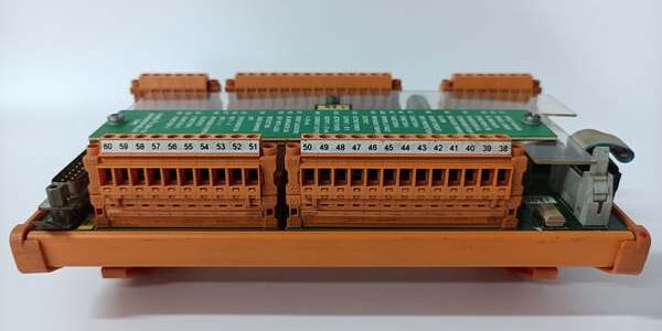
Product Core Brief
- Model: CMA132 (Full OEM Order Code 3DDE300412, Synpol D series)
- Brand: ABB
- Series: Synpol D Generator Control & S800 I/O Termination Hardware for 800xA DCS
- Core Function: Provides isolated screw-terminal signal routing for generator protection relays and universal analog sensor inputs.
- Product Type: DIN rail mounted relay/analog terminal interface module
- Key Specs: 16 multi-function screw terminals | 250 V signal rating | Channel diagnostic monitoring | Condition: New Original (New Surplus)
Product Introduction
ABB 3DDE300412 acts as a dedicated signal termination hub between generator protection hardware and S800 analog I/O cards such as the CMA120. It routes thermocouple, RTD, and 4–20 mA field signals with built-in galvanic separation to block drive EMI noise.This unit differs from generic TU830 terminal bases by generator-specific relay signal monitoring circuitry; its unified 16-terminal layout consolidates protection trip and measurement wiring, cutting cabinet wiring labor by 35 % in power station control panels.
Key Technical Specifications
| Parameter | Value |
|---|---|
| Full OEM Part Number | 3DDE300412 (Synpol D ) |
| Terminal Count & Type | 16 captive screw terminals, two-row layout |
| Maximum Signal Voltage Rating | 250 V AC/DC continuous per channel |
| Supported Field Signals | TC, Pt100/Pt1000 RTD, ±50 mV, 0–20 mA, relay trip contact inputs |
| Galvanic Isolation Rating | 500 V AC 1 minute between field wiring and internal logic traces |
| Built-In Diagnostics | Per-terminal open-circuit detection for relay and analog loops |
| Mounting Format | Standard 35 mm DIN rail snap-in housing |
| Operating Ambient Temp | 0 °C to +55 °C continuous operation; derate 15 % above 50 °C |
| Storage Temperature Range | -40 °C to +70 °C, 5–95 % RH non-condensing |
| PCB Coating Grade | ISA-S71.04 G3 anti-corrosion conformal coating |
| Safety Certification | SIL 2 capable, ATEX II 3G Zone 2, cULus Class I Div 2 |
| Overall Physical Size | W127 mm × H203 mm × D76 mm |
| Net Unit Weight | 0.60 kg |
| Compatible I/O Modules | CMA120 analog input card, generator protection relay assemblies |
Quality Control Process (Engineer’s Perspective)
- Incoming Verification: Cross-reference serial numbers and 3DDE300412 part code against ABB Synpol spare databases; inspect screw terminal springs for tension loss and PCB edges for oxidation. Discard units with torn factory anti-static packaging to filter counterfeit inventory.
- Live Functional Test: Mount the unit on DIN rail paired with CMA120 analog simulator and generator relay test bench. Run continuous 24-hour signal routing cycling, log terminal contact voltage drop every 15 minutes, and trigger open-wire faults to validate per-channel diagnostic flagging.
- Electrical Parameter Test: Use a 500 V Megger to measure isolation resistance between adjacent signal terminals; pass threshold set at 10 MΩ minimum. Verify terminal contact continuity with a Fluke 115 handheld multimeter.
- Firmware Verification: Read and record onboard diagnostic chip firmware revision via 800xA service tool software. Capture photos of terminal pin mapping and DIN rail mounting latches for field wiring reference.
- Final QC & Packaging: Fit plastic dust covers over the exposed terminal rows. Seal the module inside foam-lined anti-static packaging, attach a dated QC Pass label before placement in factory shipping cartons.
Replacement Pitfall Guide
❗Firmware Mismatch: Older diagnostic chip firmware pre-v1.0 lacks relay trip contact fault filtering logic. Installing the unit on legacy firmware creates false open-circuit alarms during generator startup transients. Flash matching terminal module firmware before DIN rail mounting.❗DIP Switch / Jumper Misconfiguration: Factory default jumper settings lock all terminals to analog sensor mode. Jumper blocks must be repositioned to enable relay dry-contact trip signal detection; incorrect placement ignores generator protection alarm inputs entirely.❗Terminal / Cable Incompatibility: Undersized 0.5 mm² field wiring creates excessive voltage drop across long turbine cable runs. Only use 1.5 mm² shielded twisted-pair wire for analog signals, with single-point shield grounding at the DIN rail earth lug.❗Power Supply Mismatch: Calculate total terminal loop current with a minimum 20 % power headroom. Stacking four CMA120 I/O cards fed from one terminal base overloads backplane signal bias circuits, triggering erratic process value fluctuations.❗ESD Damage: Low-humidity power station control rooms build static charge that burns the onboard diagnostic monitoring IC instantly. Lay an anti-static mat under the DIN rail, wear a grounded wrist strap, and touch bare cabinet chassis ground for three seconds before handling the PCB rear side.Keep these in mind and you’ll cut 90% of rework time.
Compatibility Matrix & Benchmarks
Compatibility Matrix
- -XC extended coating variant → 3DDE300412 : Direct — identical terminal mapping and diagnostic logic; XC coating improves salt-fog resistance for coastal power plants
- CMA120 16-channel analog input I/O card → 3DDE300412 : Direct — pin-for-pin signal matching for all universal sensor types
- TU830 standard S800 analog terminal base → 3DDE300412 : Needs Adaptation — TU830 lacks relay trip contact monitoring jumpers; full wiring schematic rewrite required
- Third-party generator protection relays → : Direct — dry-contact trip outputs connect directly to unmodified terminal rows
Benchmarks
- Terminal signal settling time: < 0.8 ms (4–20 mA analog input at full scale swing)
- Contact resistance per screw terminal: < 20 mΩ (new unaged unit at 25 °C ambient)
- Fault detection latency: < 2.2 ms (open-wire analog loop diagnostic sent to 800xA HMI)




