
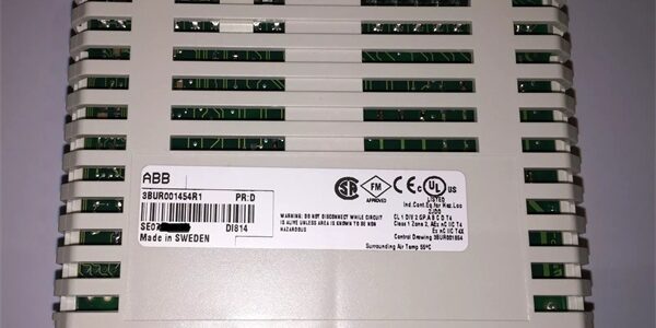
Product Core Brief
- Model: DI814, base part number 3BSE008510R1
- Brand: ABB
- Series: S800 I/O distributed fieldbus I/O platform for AC800M / System 800xA Harmony DCS controllersABB Group
- Core Function: Read 24VDC sourcing discrete contact signals from limit switches, proximity sensors, motor/valve feedback dry contacts; software configurable digital debounce eliminates mechanical contact bounce nuisance alarms
- Product Type: Slide-in compact S800 I/O module, compatible with TU810 / TU812 / TU814 / TU818 / TU830 series MTU terminal base unitsABB
- Key Specs: 16 input channels split into 2 galvanically isolated groups of 8 | 24VDC sourcing (positive common) only | 500VAC group-to-backplane dielectric isolation | Selectable 2/4/8/16ms digital filter | Hot-swap certifiedNote: Mass-deployed mainstream S800 DCS I/O module, stocked inventory is New Surplus with intact factory anti-static sealed packaging.
Key Technical Specifications
- Module logic supply: Powered via S800 fieldbus backplane, typical power dissipation 1.8W
- Nominal field input voltage: 24VDC ±20%
- Logic signal thresholds (EN 61131-2 Type 1):Logic 0: −30 V … +5 VLogic 1: +15 V … +30 V
- Input impedance: 3.5 kΩ per channel, sourcing topology only (positive common sensor wiring)ABB Group
- Channel grouping: Two electrically separated 8-channel banks with independent galvanic isolation
- Dielectric isolation rating: 500VAC between each group and I/O backplane busABB
- Digital debounce filter: Four software-selectable filter times (2, 4, 8, 16 ms) via Control Builder M
- Circuit protection: Per-channel reverse voltage blocking, integrated TVS surge clamping for motor switching EMI, continuous 30VDC overvoltage withstand
- Diagnostics: Individual yellow LED channel status indicators, green RUN power LED, group fault red alarm LEDs on front faceplate
- Max field cable length: 600m with shielded twisted pair wiring
- Operating temperature range: −25°C to +60°C full rated channel load
- Storage environmental limits: −40°C to +70°C, 5%–95% RH non-condensing
- Physical dimensions: W45 × H102 × D119 mm; unit mass 0.15kg
- Mounting: TS35 DIN rail via matched TU81x screw terminal MTU base
- Compliance standards: CE, UL, RoHS, IEC 61000-6-2 Class A industrial EMC, EN 61010 safety certification
- System compatibility: ABB AC800M / System 800xA Harmony DCS local racks, Profibus DP / Foundation Fieldbus remote I/O stations; incompatible with Mod300 S100, AC500 S500, Advant Master S400 legacy platforms
Product Introduction
This high-density 16-channel sourcing digital input module expands AC800M DCS discrete signal capacity for heavy industrial refinery, power, pulp & paper and chemical process racks. Dual isolated channel groups limit fault propagation, so a shorted field sensor cable only disables an 8-channel subgroup instead of all 16 sensing points. is the positive-common counterpart to sinking DI810, designed for plant sites that wire sensor positive to field power and negative to module input terminals. Four-step software debounce filtering suppresses false HMI alarms generated by worn mechanical limit switches. The module supports both local main rack installation and remote fieldbus I/O stations to extend DCS signal coverage across large plant sites without running hundreds of individual sensor wires back to the control room.
QA & Testing SOP (Transparency Building)
- Incoming Inspection: Cross-reference serial numbers against ABB component trace databases; inspect rear gold edge connector pins for oxidation, front channel LED segment integrity, PCB conformal coating for peeling; verify factory static packaging seal remains unbroken for surplus stock.
- Live Testing: Mate the unit to a TU810 terminal base on a DIN rail test bench paired with an AC800M controller simulator and sourcing dry contact signal generators; run uninterrupted 24-hour cyclic channel state polling across all four debounce timing settings; use a Fluke 115 to log steady 24VDC field supply voltage through the full test cycle.
- Electrical Testing: Perform 500VAC hipot insulation testing between each 8-channel isolated group and backplane logic ground; pass threshold set at >10MΩ insulation resistance; inject reversed 24VDC and transient surge faults to confirm hardware protection activates without damaging input optocoupler semiconductors.
- Firmware/Config Backup: Record factory module interface firmware revision via Control Builder M engineering software; photograph TU81x terminal pin layouts and document factory default debounce filter values for field commissioning reference.
- Final QC & Packaging: Torque all TU81x base terminal screw connections to OEM torque specifications; enclose the module in static-dissipative foam; attach a printed QC tag listing serial number and completed test metrics before carton sealing.
Installation Pitfalls & Guide (Engineer to Engineer)
❗DCS Controller Firmware Mismatch Risk: Outdated AC800M CPU firmware lacks calibrated debounce register and group fault register mapping for the module. Fault outcome: Unfiltered contact bounce generating false discrete status alarms, delayed safety interlock response during process load transients. Mitigation: Flash matching validated firmware revisions to the controller before rack power-up; archive compatible firmware files to plant engineering servers.❗Sink Sensor Wiring Mismatch Risk: only supports sourcing inputs; connecting sinking 24VDC sensors results in permanently OFF channel readings with no LED activity. Fault outcome: Complete loss of affected group measurement. Mitigation: Reconfigure field wiring to positive common sourcing topology or swap to DI810 sinking input module for negative common sensor circuits.❗Overvoltage Field Signal Risk: Connecting 48VDC sensor circuits to the 30VDC maximum rated input terminals burns internal optocoupler components permanently. Fault outcome: Complete loss of affected 8-channel group with no recoverable operation. Mitigation: Measure all discrete circuit voltage levels via multimeter before terminating wiring to the TU81x base terminals.❗Terminal Base Incompatibility Risk: Attempting to mount the module to non-TU81x series base units creates misaligned edge connector pinouts and unregulated supply exposure. Fault outcome: Burned input circuit semiconductors, permanent module failure. Mitigation: Only deploy the unit paired with OEM TU810, TU812, TU814 terminal base assemblies.❗Shared Common Ground Wiring Error: Jumping positive return lines across separate isolated 8-channel groups breaks group galvanic separation performance. Fault outcome: Cross-group signal bleed creating fluttering open/closed sensor status readings during motor contactor switching transients. Mitigation: Maintain isolated positive return wiring for each individual 8-channel group per the TU terminal wiring schematic.❗ESD Dangers: Low-humidity refinery control room air generates static charge that damages delicate input optocoupler ICs on the PCB. Field service logs show ungrounded handling creates intermittent flickering discrete status faults that require multiple diagnostic shifts to isolate. Mitigation: Establish direct contact with bare cabinet chassis ground metal for three full seconds before touching module edge connectors or base terminal blocks.
4-Step Replacement Guide
- Pre-install: Set the controller to manual hold mode to freeze all discrete interlock logic values; photograph all limit switch and valve feedback wiring assignments on the TU81x terminal base assembly, and record current debounce filter parameter settings in Control Builder M.
- Removal: Slide the module straight upward out of the TU81x base without bending edge connector pins; leave all field wiring terminated to the base to eliminate full retermination labor.
- Install: Align the new unit’s rear edge connector with the TU81x base slot and slide fully seated until the module retention tab locks into place; replicate debounce timing and group fault monitoring parameter configurations within Control Builder M to match original process requirements.
- Power-on Test: Energize 24VDC field supply; toggle simulated open/closed sourcing contact signals to all 16 input channels via signal simulator, confirm consistent discrete state reporting with zero group fault flags accumulating during 30 minutes of idle channel polling before restoring live process control logic.
FAQ (Frequently Asked Questions)
Q: What is the core difference between and DI810?A: DI810 = 16-channel 24VDC sinking (negative common); = 16-channel 24VDC sourcing (positive common). All channel count, isolation, debounce, terminal base and firmware features are identical, only sensor wiring polarity differs.Q: Does this module support hot-swapping while the TU terminal base remains energized?A: Hot-swap is rated and supported for the I/O platform, but manual hold mode must still be enabled on the controller to prevent unplanned safety interlock trips during the swap window. Hot-swap only protects internal module semiconductors from power transients.Q: What warranty coverage applies to surplus stocked units?A: A 12-month limited warranty only covers factory manufacturing defects. Damage from sinking sensor wiring mismatch, overvoltage field inputs, ungrounded ESD handling, incompatible TU terminal bases, or sustained channel wiring short-circuits is excluded from warranty claims.Q: If a single channel inside an 8-channel group fails, can individual optocoupler components be repaired on-site?A: Field repair of damaged input circuits is not recommended for critical safety interlock systems. Repaired PCB trace paths degrade group isolation performance and raise risk of false safety trip events; full module swap is the standard site maintenance procedure.Q: Can multiple units share a single 24VDC field power circuit in one rack?A: Multiple units may share one 24VDC supply only if the supply unit maintains 20% extra current headroom above total combined module power draw. Independent auxiliary feed wiring is recommended for racks with six or more installed digital input modules to eliminate voltage sag during simultaneous channel polling events.Q: Is this sourcing digital input module rated for Class 1 Div 2 hazardous cabinet deployment inside refinery pump MCC rooms?A: No, the open slide-in module + TU base design lacks intrinsic safety certification for flammable vapor environments. Flameproof dedicated I/O enclosures are required for hazardous area process installations.Q: What long-term upgrade path exists as this component reaches end-of-life support?A: remains the standard 16-point sourcing DC input module for all new System 800xA deployments. For distributed multi-cabinet systems, ABB recommends Profibus/Foundation Fieldbus remote I/O stations populated with to extend DCS signal capacity without expanding main control rack footprint.




