
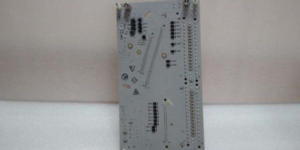
Product Core Brief
- Model: CC-TDOB01
- Brand: Honeywell
- Series: Experion PKS C300 Series-C Digital Output Simplex IOTA
- Core Function: 6-inch simplex termination base to wire 32-channel PNP source digital outputs for standard 24VDC process solenoids and control relays
- Product Type: Simplex Sourcing Digital Output IOTA (Input Output Termination Assembly)
- Key Specs: 32 field channels | Simplex single signal bus | 0.5A per channel load capacity | Spring compression screw terminalsNote: Discontinued end-of-life hardware, stocked exclusively as unopened New Surplus inventory; redundant counterpart = CC-TDOB11.
Key Technical Specifications
- Compatible IOM: CC-PDOB01 32-channel high-current sourcing digital output IOM
- Channel Count: 32 discrete output channels grouped into four 8-channel banks
- Field Operating Voltage: 18–30VDC nominal 24VDC PNP sourcing circuit
- Per-Channel Continuous Load Rating: 0.5A resistive/moderate inductive solenoid loads
- Terminal Style: Spring-clamp screw terminals, accepts AWG16–22 solid/stranded copper wire
- Onboard Circuitry: Per-channel PTC foldback current limiting, transient surge suppression, RC flyback snubber networks for inductive loads
- Mount Format: DIN rail mount, direct edge mating connector to the paired IOM
- Backplane Operating Voltage: 18VDC to 36VDC rack supply
- Ambient Operating Temperature: -40°C minimum to +70°C maximum cabinet ambient
- Hazardous Location Approval: FM Class I Div 2 Groups A/B/C/D cabinet mounting certified
- Environmental Coating: Full conformal coated PCB for corrosive refinery and offshore cabinet atmospheres
- Physical Dimensions: 152mm H × 52mm W × 175mm D; net weight 0.39kg
Product Introduction
This simplex termination base routes all 32 PNP source output signals from the matching IOM to field solenoid and relay wiring. Integrated PTC limiting and flyback snubbers contain short-circuit and inductive flyback faults before damage propagates to the rack IOM electronics.Spring-clamp terminals cut marshalling cabinet wiring time versus fixed screw lug designs, while banked channel grouping simplifies targeted fault isolation during unplanned process trips.
QA & Testing SOP (Transparency Building)
- Incoming Inspection: Cross-reference serial barcodes against Honeywell OEM batch manifests; inspect PCB for cracked traces, bent IOM edge connectors, and damaged terminal springs; verify factory anti-static bag seal integrity.
- Live Testing: Mated with spare CC-PDOB01 on a bench C300 rack powered by a Fluke 115 regulated 24VDC supply; run 24-hour cyclic channel toggle testing with simulated short-circuit inductive load injection across all 32 channels.
- Electrical Testing: Megger insulation test >10MΩ between each output channel and IOM mating connector bus; confirm PTC foldback activates consistently above 0.6A per channel overcurrent threshold.
- Firmware/Config Backup: No onboard local firmware storage; capture high-resolution photos of sink/source mode jumpers for field service reference before bench testing.
- Final QC & Packaging: Attach serialized printed test pass tag; seal unit in foam-lined static-shielded bag to protect edge mating pins during warehouse storage and transit.
Installation Pitfalls & Guide (Engineer to Engineer)
❗ Firmware Rev Compatibility Risk: Experion PKS R401 and newer releases enforce stricter output load mismatch fault alarms; lock rack controller firmware to R400 or older before base swap to avoid constant minor fault alerts.❗ Jumper Configuration Loss: Capture high-res photos of PNP sourcing mode jumpers on the removed old unit; misconfigured sink/source jumpers reverse coil polarity and trigger unplanned ESD valve trips.❗ Wiring Incompatibility: This simplex base pinout does not interchange with redundant CC-TDOB11; swapping without full harness retermination disables half the redundant signal path for paired IOM deployments.❗ Inductive Load Miscalculation: Large solenoid coils without external snubbers exceed internal flyback suppression limits; add parallel freewheeling diodes across all heavy inductive field devices.❗ ESD Component Damage Risk: Ungrounded technicians have destroyed signal filter circuits during IOM swap-outs; latent damage creates intermittent channel dropout that surfaces after 2–3 weeks of continuous runtime.
4-step replacement guide:
- Pre-install: Activate cabinet LOTO on 24VDC field power; secure grounded anti-static wrist strap to DIN rail ground lug.
- Removal: Document sourcing jumper positions via photo; unlatch the IOM from the base edge connector, remove each field wire one channel at a time, slide the unit off DIN rail.
- Install: Mount new hardware to DIN rail, replicate all jumper settings from reference photos, reterminate field wiring to matching channel slots, fully seat and lock the CC-PDOB01 IOM onto the edge connector.
- Power-on Test: Restore field power; open Control Builder diagnostic screens to confirm zero active short-circuit or load mismatch fault flags across all 32 output channels.
FAQ (Frequently Asked Questions)
Q: Can this simplex termination base be used in 1:1 redundant digital output rack configurations?A: No. This unit only contains a single isolated signal bus. Redundant 32-channel source output pairs require CC-TDOB11, which includes dual mirrored field wiring buses and cross-check signal routing to the paired backup IOM. Using this simplex base in a redundant slot breaks full fault coverage required for IEC 61511 critical control loops.Q: Does the assembly support hot-swapping of the paired IOM while the C300 rack remains energized?A: The IOM hardware supports rack hot-swap, but field 24VDC power must be fully isolated before disconnecting the edge mating connector from the base. Live field power disconnection induces inductive voltage transients that damage the onboard snubber filter networks on the PCB.Q: What warranty coverage applies to bench-tested surplus stocked units?A: All inventory units carry a 12-month functional warranty covering factory PCB, terminal spring, and PTC limiting circuit defects. Damage from unfiltered inductive flyback, misconfigured source/sink jumpers, or ungrounded ESD handling is excluded from all coverage terms.Q: Is there a direct drop-in modern replacement for this discontinued termination hardware?A: Current Series-C digital output IOTAs integrate matching PNP sourcing circuitry, but full field harness retermination and Control Builder output load logic revalidation is mandatory; edge connector impedance and fault reporting pinout do not match for unmodified direct swap.Q: What fault isolation do the banked PTC limiters provide during field wiring shorts?A: Each 8-channel bank uses independent current limiting circuits; a shorted solenoid wire only locks out a single channel within its bank, leaving the remaining 31 discrete control outputs fully functional for process interlock visibility.Q: Can this base be paired with low-current sinking CC-PDOD51 IOM hardware?A: Not supported. The edge connector pinout and onboard sourcing power rails are engineered exclusively for CC-PDOB01 PNP high-current IOM hardware. Mismatched sink IOM pairing produces zero output drive and permanent terminal circuit overload damage within minutes of power application.Q: Can multiple field solenoids be wired in parallel to a single output channel terminal?A: Permitted only if combined total coil current stays below the 0.5A per-channel continuous rating. Parallel loads exceeding this threshold trigger persistent PTC current limiting and repeated minor rack fault alarms during normal operation.




