
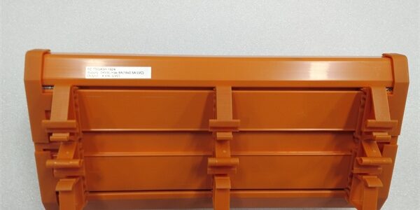
Product Core Brief
- Model: FC-TSGAS-1624
- Brand: Honeywell
- Series: FSC / Safety Manager Fire & Gas (F&G) SIL Safety Platform
- Core Function: DIN rail field termination assembly that conditions 4–20mA signals from combustible/toxic gas detectors and converts to 0–4V for the paired safety analog IOM
- Product Type: Fire & Gas Safety Analog Input FTA
- Key Specs: 16 isolated channels | 24VDC field loop power | Per-channel slow-blow fuses | Conformal coated PCBNote: Discontinued end-of-life hardware, stocked exclusively as unopened New Surplus inventory.
Key Technical Specifications
- Compatible IOM: FC-SGAS-1624 16-channel fire/gas safety analog input module
- Supported Field Signal: 4–20mA two-wire gas/flame detectors; internal conversion to 0–4V for rack IOM
- Channel Count: 16 galvanically separated input channels, grouped two banks of eight
- Field Operating Voltage Range: 20–32VDC nominal 24VDC detector supply
- Terminal Type: Screw compression terminals; max wire gauge AWG14, torque 0.5Nm
- Overcurrent Protection: 315mAT slow-blow fuse per individual channel
- Integrated Circuitry: 250Ω precision load resistors, transient surge suppression, EMI filter networks
- Mount Standard: TS35 DIN rail fixed mounting
- Operating Ambient Temperature: -40°C to +70°C cabinet temperature
- Hazardous Area Rating: FM Class I Div 2 Groups A/B/C/D cabinet installation approved
- Environmental Coating: Full PCB conformal coating for corrosive refinery/offshore cabinet environments
- Physical Dimensions: 225mm L × 70mm W × 60mm D; unit weight 0.52kg
Product Introduction
This termination base handles all field-side signal conditioning for fire and gas safety detectors, isolating wiring shorts and voltage transients before faults propagate to the rack-mounted safety IOM. Its dedicated 250Ω precision resistors translate standard 4–20mA gas sensor outputs to the fixed 0–4V input range required by the matching SIL-rated safety card.Per-channel fused protection limits fault impact to a single detector loop, a mandatory design element to meet IEC 61508 SIL3 fault coverage requirements for continuous process hazard monitoring.
QA & Testing SOP (Transparency Building)
- Incoming Inspection: Cross-reference serial barcodes against OEM factory batch records; visual scan for cracked PCB substrate, bent terminal lugs, or damaged ribbon edge connectors; verify original factory anti-static packaging seal integrity.
- Live Testing: Mated to a spare FC-SGAS-1624 on a bench Safety Manager rack powered by a Fluke 115 regulated 24VDC supply; run 24-hour continuous channel ramp cycling with simulated open-loop and short-circuit fault injection on all 16 channels.
- Electrical Testing: Megger insulation resistance test >10MΩ between each field channel and ribbon bus pins; confirm each channel fuse trips consistently above 25mA overcurrent threshold.
- Firmware/Config Backup: No onboard local firmware storage; capture high-resolution photos of factory default channel grouping jumpers for field service reference.
- Final QC & Packaging: Affix serialized printed test pass tag; seal unit in foam-lined static-shielded bag to protect ribbon connector pins during warehouse storage and transit.
Installation Pitfalls & Guide (Engineer to Engineer)
❗ Firmware Rev Compatibility Risk: Safety Manager R150 and older software releases lack full gas detector fault diagnostic logic; upgrade rack logic solver firmware to R160 or newer before replacement to avoid unreported sensor drift and open-loop blind faults.❗ Jumper Configuration Loss: Photograph jumper bank positions on the old unit prior to removal; misconfigured channel grouping jumpers lock out full banks of gas detector signals from safety logic scans.❗ Wiring Incompatibility: This assembly’s ribbon pinout does not match general-purpose FC-TSAI series FTAs; cross-substitution without full field harness retermination creates unreadable gas concentration PV values and permanent filter circuit damage.❗ Loop Resistance Miscalculation: Combined field cable + sensor resistance exceeding 650Ω collapses the 20mA full-scale signal; install inline loop booster power supplies for field detector runs longer than 750 meters.❗ ESD Component Damage Risk: Ungrounded technicians can discharge static into the ribbon connector filter circuitry; unprotected handling has destroyed paired IOM/FTA hardware valued over $2,100 during site swap-outs.
4-step replacement guide:
- Pre-install: Lock out field 24VDC detector power; secure grounded anti-static wrist strap to cabinet DIN rail ground lug.
- Removal: Document channel grouping jumper positions via high-res photo; disconnect ribbon cable lock tab, remove each field detector wire sequentially, slide the unit off TS35 DIN rail.
- Install: Mount new unit to DIN rail, replicate all jumper settings from reference photos, reterminate field wiring to matching channel screw terminals, fully seat and lock the ribbon cable connector to the paired safety IOM.
- Power-on Test: Restore field detector power; open Safety Builder diagnostic screens to confirm zero active open/short loop faults and stable gas concentration readings across all 16 channels.
FAQ (Frequently Asked Questions)
Q: Can this termination base operate in redundant SIS fire/gas rack configurations?A: No. This unit is simplex-only. Redundant SIL3 fire and gas monitoring pairs require the matching redundant FTA variant, which includes dual isolated field wiring buses and cross-check signal routing to the backup IOM. Using this simplex part in a redundant slot breaks full fault detection coverage required for IEC 61508 compliance.Q: Does the assembly support hot-swapping while the Safety Manager rack remains energized?A: The rack IOM module supports hot-swap removal, but field 24VDC detector power must be fully isolated before detaching the ribbon cable from the base. Live field power disconnection induces voltage transients that damage the analog signal filter networks on the FTA PCB.Q: What warranty coverage applies to bench-tested surplus stocked units?A: All inventory units carry a 12-month functional warranty covering factory PCB, terminal, and signal conditioning circuit defects. Damage from field surge overload, misconfigured grouping jumpers, or ungrounded ESD handling is excluded from coverage terms.Q: Is there a direct drop-in modern replacement for this discontinued hardware?A: Honeywell’s current-generation universal safety termination hardware supports fire/gas detectors, but full field harness retermination and Safety Builder gas hazard logic revalidation is mandatory; ribbon pinout and channel fault reporting logic do not match for unmodified direct swap.Q: What fault isolation do the integrated per-channel fuses provide?A: Slow-blow 315mAT fuses contain field wiring short-circuit faults to a single detector channel, maintaining partial gas hazard visibility across the remaining 15 sensor loops during single-point field failure events, a mandatory SIL3 design requirement.Q: Can this FTA be paired with 0–5V voltage output flame detectors?A: No. The internal signal conditioning circuits are hardwired exclusively for 4–20mA two-wire loop-powered gas/flame sensors. Connecting voltage-output devices overloads the 250Ω load resistors and produces invalid concentration readings in the safety logic solver.Q: Can a general-purpose FC-TSAI analog FTA substitute this fire/gas dedicated base for detector wiring?A: Not recommended. General-purpose safety FTAs lack optimized EMI filtering for high-noise refinery F&G field wiring, leading to frequent false high-concentration gas alarms and degraded SIL diagnostic coverage for fire hazard loops.




